Page 10 of 18 FirstFirst ... 67891011121314 ... LastLast
Results 181 to 200 of 352

Thread: MPSciLink

  1. #181
    Supporting Member Turbo Mopar Contributor
    Join Date
    Feb 2015
    Location
    toronto
    Posts
    1,765
    Regards,
    Miles

    DD '87 Sundance T1, SLH with rear disks
    '87 CSX #432 2.5 CB TII, SLH

  2. #182
    Slugmobile & MeanMini Caretaker Turbo Mopar Contributor wheming's Avatar
    Join Date
    Nov 2010
    Location
    Raleigh Area, NC
    Posts
    4,809

    Re: MPSciLink

    The first few orders have been shipped out and starting to see some delivery confirmations in tracking.
    If anyone has any questions or issues when setting up, we can provide some help.
    I've done some videos to try to assist in setup.
    MPSciLink testing & demo videos: http://www.youtube.com/playlist?list...fr3CnSghbGspw3

    I thought about trying to do live cast youtube if that would help, but i have Hangouts and Messenger for video calls if needed.
    I haven't had any time to do any written manuals.
    Wayne H.

    '91 Dodge Spirit ES 2.5L turbo 5spd
    '05 PT GT 2.4T HO autostick (RIP)
    '89 Plymouth Acclaim 2.5L turbo auto, "Slugmobile" yes, THE Slugmobile!
    '89 Dodge Caravan SE 2.5L turbo auto, "Mean Mini" yes, Gus' Mean Mini! (Current best 11.699 @ 114.43 mph! - Oct 15th, 2022 Cecil County Dragway, MD)
    MeanMini dragracing videos: https://www.youtube.com/playlist?lis...URZLB1RxGYF6vw
    and other cars, trucks and motorcycles
    https://www.youtube.com/user/SlugmobileMeanMini

  3. #183
    Hybrid booster
    Join Date
    Mar 2009
    Location
    Tampa Bay
    Posts
    382

    Re: MPSciLink

    Are the overall dimensions of the 3.5" screen with the protective display listed anywhere? Looked but could not find.

    Thanks,

  4. #184
    Slugmobile & MeanMini Caretaker Turbo Mopar Contributor wheming's Avatar
    Join Date
    Nov 2010
    Location
    Raleigh Area, NC
    Posts
    4,809

    Re: MPSciLink

    Quote Originally Posted by EaZyE426 View Post
    Are the overall dimensions of the 3.5" screen with the protective display listed anywhere? Looked but could not find.

    Thanks,
    I could get you the measurements tomorrow evening.
    Wayne H.

    '91 Dodge Spirit ES 2.5L turbo 5spd
    '05 PT GT 2.4T HO autostick (RIP)
    '89 Plymouth Acclaim 2.5L turbo auto, "Slugmobile" yes, THE Slugmobile!
    '89 Dodge Caravan SE 2.5L turbo auto, "Mean Mini" yes, Gus' Mean Mini! (Current best 11.699 @ 114.43 mph! - Oct 15th, 2022 Cecil County Dragway, MD)
    MeanMini dragracing videos: https://www.youtube.com/playlist?lis...URZLB1RxGYF6vw
    and other cars, trucks and motorcycles
    https://www.youtube.com/user/SlugmobileMeanMini

  5. #185
    Slugmobile & MeanMini Caretaker Turbo Mopar Contributor wheming's Avatar
    Join Date
    Nov 2010
    Location
    Raleigh Area, NC
    Posts
    4,809

    Re: MPSciLink

    Had a bit of time before wotk...
    4"x2.5"×<0.5"

    Click image for larger version. 

Name:	uploadfromtaptalk1517406330907.jpg 
Views:	87 
Size:	72.9 KB 
ID:	62094
    Click image for larger version. 

Name:	uploadfromtaptalk1517406348294.jpg 
Views:	93 
Size:	64.9 KB 
ID:	62095
    Click image for larger version. 

Name:	uploadfromtaptalk1517406369410.jpg 
Views:	81 
Size:	69.4 KB 
ID:	62096
    Wayne H.

    '91 Dodge Spirit ES 2.5L turbo 5spd
    '05 PT GT 2.4T HO autostick (RIP)
    '89 Plymouth Acclaim 2.5L turbo auto, "Slugmobile" yes, THE Slugmobile!
    '89 Dodge Caravan SE 2.5L turbo auto, "Mean Mini" yes, Gus' Mean Mini! (Current best 11.699 @ 114.43 mph! - Oct 15th, 2022 Cecil County Dragway, MD)
    MeanMini dragracing videos: https://www.youtube.com/playlist?lis...URZLB1RxGYF6vw
    and other cars, trucks and motorcycles
    https://www.youtube.com/user/SlugmobileMeanMini

  6. #186
    Hybrid booster
    Join Date
    Mar 2009
    Location
    Tampa Bay
    Posts
    382

    Re: MPSciLink

    Thank you Wayne. Looking into mounting solutions for when the next group buy kicks into gear.

  7. #187
    Supporting Member Turbo Mopar Contributor
    Join Date
    Feb 2015
    Location
    toronto
    Posts
    1,765

    Re: MPSciLink

    Hello DIYer,
    I wanted to start a post on the assembly of a DIY kit. I am super busy with assembly/testing so I will add items to this post as questions arise.
    First off, the silkscreen has most parts labelled so this should be easy. I will post a photo for all to see.
    I usually start with the SMD components as they are small.
    We needed to design the board based on photos and other info from our Chinese suppliers. This was done to keep the cost reasonable. The are a few area that need a wee bit of tweaking during assembly
    1)small signal diode(top right) for unswitched +12V lead needs to be bent down slightly to clear screw terminal connection.
    2)several points for components are ground and since I use a large ground plane on the board you may need need more juice if you are using a hobby quality soldering iron. My Hakko 888D works a dream with a 3.2mm chisel tip for all soldering including the SMD components on this board.
    3)Just a bit above the +12V connector near the bottom left is the MOV(my silkscreen says R25, My Bad?)
    4) the Ti-431 Voltage reference is hand selected by bored Canadians to provide as close to 5.00 V as possible. A few were out by 0.02V and this was corrected once again by bored Canadians by hand matching precision 10K to ultimately provide 5.00V at AREF of the micro. The precision 10K resistors were matched using a DER EE DE-5000 High Accuracy Handheld LCR Meter. The resistor that connects to ground is wrapped with green tape and labelled GND
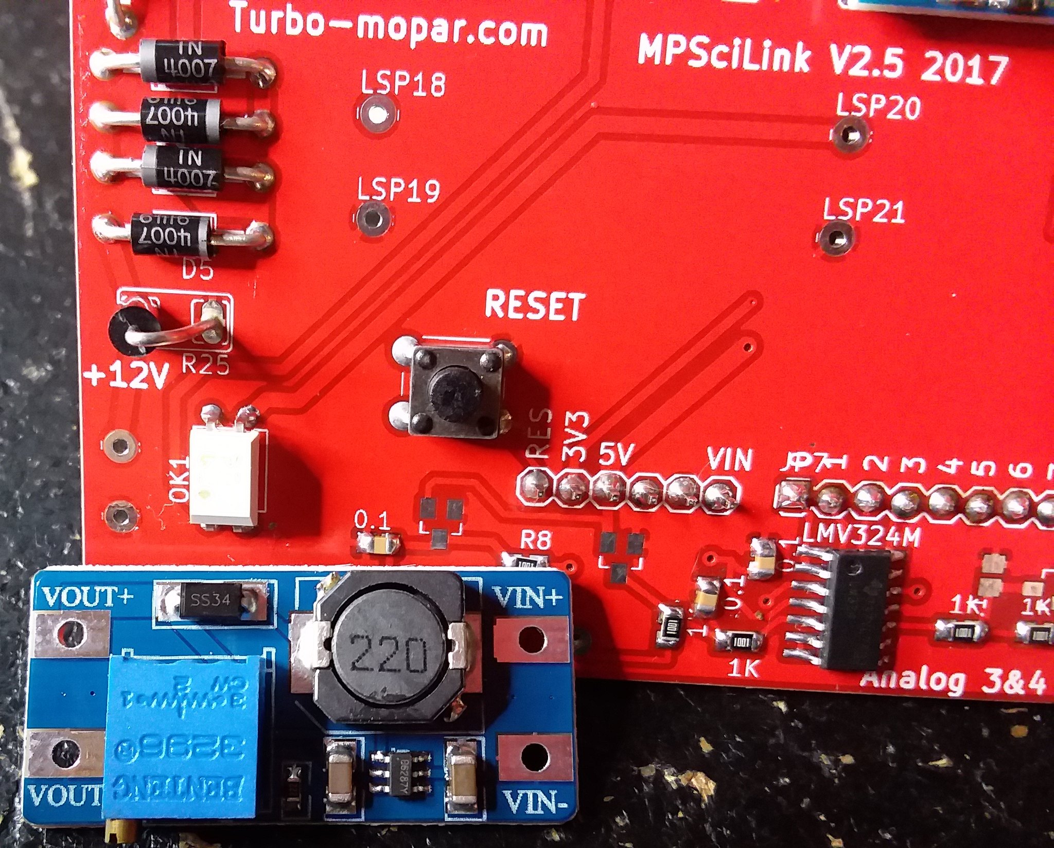
    5)DC-DC module holes are a touch different from our supplier,but a little wiggle and it will be fine.
    6)Install BT AFTER the DC-DC as they are very close and may touch. It is OK if the bottom of the BT is above the top of the DC-DC but usually they touch but only slightly.
    7)I have modified the pin orientation of the BT for you but you will need to do the same task to the SD card module.
    8)Analog #4 0805 1K and 0.1uF passives are interfering with the screw terminal. Just take a box cutter and shave a bit of plastic of the bottom of a the screw connector to clear the passives.
    9)The Arduino pins library I used don't have all the pins in perfect straight line but it works fine. When installing pins place the pins in the Board and assemble carefully into to mega. Adjust the pin heights and solder. No big deal but some will think "huh?"
    10) I use my Hakko at 700F and it works great with 0.5mm rosin solder. Our boards are very good for rework if you make a boo boo just keep the iron temperature at a reasonable temperature. A good pair of electronic cutters are useful.
    11) Please note L1 is a jumper at this time. You can use a piece of trimmed 1N400X lead.
    12) Only populate the top and bottom six pins of the large Arduino connector on the right side.

    Note how to modify SD card modules for use.
    I discovered a great and fast method for exchanging pins on BT and SD card modules
    1)Cut off excess pins.
    2)Remove/pry black pin support with a small precision screwdriver
    3) desolder old pin and pullout with pliers/hemostat
    4) heat and push through hole SS desolder tool ( $2 for the entire kit from ebay https://www.ebay.ca/itm/8Pc-Stainles...UAAOSw8w1X-baG)
    5) install/solder new header in opposite direction as original module

    Enjoy!

    Send me a PM if you would like to use my Arduino sketch for testing
    Last edited by chromguy; 03-03-2018 at 12:32 PM.
    Regards,
    Miles

    DD '87 Sundance T1, SLH with rear disks
    '87 CSX #432 2.5 CB TII, SLH

  8. #188
    Supporting Member Turbo Mopar Contributor
    Join Date
    Feb 2015
    Location
    toronto
    Posts
    1,765

    Re: MPSciLink

    Additional good news on the MPSciLink.
    Yesterday I was able to acquire a half dozen logs on my LM based ECU using MPScandroid. I have only just started to explore the functionality using the LM but thought I would update the group.
    The LM is much slower to log data than a SMEC based solution and over the next few days I will get a better idea of how the other features work in real driving conditions.
    Regards,
    Miles

    DD '87 Sundance T1, SLH with rear disks
    '87 CSX #432 2.5 CB TII, SLH

  9. #189
    Supporting Member Turbo Mopar Contributor
    Join Date
    Jun 2006
    Location
    Spearfish SD
    Posts
    2,038

    Re: MPSciLink

    appreciate this testing miles. it's good to finally get some feedback on the LM. the routines get a little bit complicated since the LM spews out the requested ram location value over and over vs just 1 time with the smec/sbec, so you have to wait for at least 2 bytes to come back and then select the last one. plus the lm sci send routine is so much slower. when you get a chance, set up a layout with 7 or 8 gauges just to see what the logging rate will be. there are some settings in mpscandroid you can play with also, but i'ld use the defaults for now.
    89 Voyager LE, 2.5T2 - rest in peace
    87 Charger Shelby T2 (2.4 conversion in process)

  10. #190
    Garrett booster
    Join Date
    May 2013
    Location
    Hartville
    Posts
    157

    Re: MPSciLink

    I mostly got my kit assembled this evening. Unfortunately, I am missing some parts. I assume they are transistors - they are the small 3 prong SMD parts. Also, I think I am missing a resistor. I was shipped 4 .01 caps, and 8 1k SMD rfesistors. The board has silkscreen for this exact quantity, but there is one place unmarked. I tried highlighting it, but it's impossible to highlight this bright red PCB. It is the empty set of pads above the "Analog 3&4 silkscreen". I was also missing a 470ohm resistor, but I have a huge kit of 1/4watt 5%, so no worries there.

    I also have a question. What is the proper orientation of the DC-DC convertor? Lastly, will this need adjusted so that I have 21V on the board or is it pre-calibrated?


  11. #191
    Slugmobile & MeanMini Caretaker Turbo Mopar Contributor wheming's Avatar
    Join Date
    Nov 2010
    Location
    Raleigh Area, NC
    Posts
    4,809

    Re: MPSciLink

    Here is a pic that may help answer some of your questions.
    Click image for larger version. 

Name:	uploadfromtaptalk1520035079227.jpg 
Views:	128 
Size:	67.1 KB 
ID:	62230

    I could get a closer pic tomorrow though if you need more detail.
    For reference this is the v2.5 assembled board. All the red PCB ones are v2.5

    And yes, you'll have to adjust up to 21.5v on that pot.
    Last edited by wheming; 03-02-2018 at 08:19 PM.
    Wayne H.

    '91 Dodge Spirit ES 2.5L turbo 5spd
    '05 PT GT 2.4T HO autostick (RIP)
    '89 Plymouth Acclaim 2.5L turbo auto, "Slugmobile" yes, THE Slugmobile!
    '89 Dodge Caravan SE 2.5L turbo auto, "Mean Mini" yes, Gus' Mean Mini! (Current best 11.699 @ 114.43 mph! - Oct 15th, 2022 Cecil County Dragway, MD)
    MeanMini dragracing videos: https://www.youtube.com/playlist?lis...URZLB1RxGYF6vw
    and other cars, trucks and motorcycles
    https://www.youtube.com/user/SlugmobileMeanMini

  12. #192
    Garrett booster
    Join Date
    May 2013
    Location
    Hartville
    Posts
    157

    Re: MPSciLink

    Quote Originally Posted by wheming View Post
    Here is a pic that may help answer some of your questions.
    Click image for larger version. 

Name:	uploadfromtaptalk1520035079227.jpg 
Views:	128 
Size:	67.1 KB 
ID:	62230

    I could get a closer pic tomorrow though if you need more detail.
    For reference this is the v2.5 assembled board. All the red PCB ones are v2.5

    And yes, you'll have to adjust up to 21.5v on that pot.
    That's perfect - thanks. So it seems that I was only given 4 .01 SMD capacitors, when I need 5, and am missing 4 I believe transistors. Thanks for the info on the DC-DC convertor - I'll finish soldering everything I can tomorrow.

  13. #193
    Supporting Member Turbo Mopar Contributor
    Join Date
    Feb 2015
    Location
    toronto
    Posts
    1,765

    Re: MPSciLink

    Quote Originally Posted by MoparStephen View Post
    That's perfect - thanks. So it seems that I was only given 4 .01 SMD capacitors, when I need 5, and am missing 4 I believe transistors. Thanks for the info on the DC-DC convertor - I'll finish soldering everything I can tomorrow.
    Hello,
    There should have been 5 of the 0805 caps and 4 BAT54S input protection Schottky. PM me your address and I will send you the missing parts via the Canada post, approx delivery of 1 week.
    Also looks like a good soldering job there!
    Regards,
    Miles

    DD '87 Sundance T1, SLH with rear disks
    '87 CSX #432 2.5 CB TII, SLH

  14. #194
    Garrett booster
    Join Date
    May 2013
    Location
    Hartville
    Posts
    157

    Re: MPSciLink

    Quote Originally Posted by chromguy View Post
    Hello,
    There should have been 5 of the 0805 caps and 4 BAT54S input protection Schottky. PM me your address and I will send you the missing parts via the Canada post, approx delivery of 1 week.
    Also looks like a good soldering job there!
    No worries - if you send me the pasrt #s, I will gladly order from a local supplier. I have accounts at several places.

    Thanks for the soldering compliments. Many years ago, I worked at a custom PCB manufacturer, I was in charge of pulling parts, stuffing boards, running wave solder, and doing testing/repair work. I must admit though - I am about of the age where I may need to stop doing SMD work and just stick more with welding Eyes aren't what they used to be.

  15. #195
    Supporting Member Turbo Mopar Contributor
    Join Date
    Feb 2015
    Location
    toronto
    Posts
    1,765

    Re: MPSciLink

    Quote Originally Posted by MoparStephen View Post
    No worries - if you send me the pasrt #s, I will gladly order from a local supplier. I have accounts at several places.

    Thanks for the soldering compliments. Many years ago, I worked at a custom PCB manufacturer, I was in charge of pulling parts, stuffing boards, running wave solder, and doing testing/repair work. I must admit though - I am about of the age where I may need to stop doing SMD work and just stick more with welding Eyes aren't what they used to be.
    This is what I use at home and at work. They look cheap but they are high quality, comfortable for us old guys. I need these for all electronics. I think mine are 2.5 plus 1.5 for my bifocals.
    https://www.amazon.com/Donegan-Optic.../dp/B0068OSIIS
    Donegan is made in the USA

    Here are the parts numbers
    https://www.digikey.ca/product-detai...68-1-ND/411443
    https://www.digikey.ca/product-detai...OSCT-ND/917811

    LMK if you want me to ship these to you.
    Regards,
    Miles

    DD '87 Sundance T1, SLH with rear disks
    '87 CSX #432 2.5 CB TII, SLH

  16. #196
    Garrett booster
    Join Date
    May 2013
    Location
    Hartville
    Posts
    157

    Re: MPSciLink

    Can you please ship these to me. I went to digi-key to order, but they are unfortunately out of the BAT54SLT1GOSCT-ND and saying there could be up to 16 weeks lead time.

    I assume that I can still power up the arduino and screen so that I can install the MPSciLink software with the board incomplete? I wouldn't be using the analog inputs so I don't see the missing protection posing a problem.

  17. #197
    Supporting Member Turbo Mopar Contributor
    Join Date
    Feb 2015
    Location
    toronto
    Posts
    1,765

    Re: MPSciLink

    Quote Originally Posted by MoparStephen View Post
    Can you please ship these to me. I went to digi-key to order, but they are unfortunately out of the BAT54SLT1GOSCT-ND and saying there could be up to 16 weeks lead time.

    I assume that I can still power up the arduino and screen so that I can install the MPSciLink software with the board incomplete? I wouldn't be using the analog inputs so I don't see the missing protection posing a problem.
    I guess I purchased them all

    Sure thing PM me your address and I will mail them tomorrow. Yes you can do everything with out the BAT54S even analog BUT you don't have any input protection from negative or higher analog voltages. This could fry the mega ADC not the end of the world as clone megas are inexpensive.
    Regards,
    Miles

    DD '87 Sundance T1, SLH with rear disks
    '87 CSX #432 2.5 CB TII, SLH

  18. #198
    Garrett booster
    Join Date
    May 2013
    Location
    Hartville
    Posts
    157

    Re: MPSciLink

    Limited success. I finished assembly today, and I was able to get MPTune to flash the arduino. 7" touchscreen is working, I can get into clock settings, calibrate the display, etc.

    Two problems I am having (perhaps this is just user error). 1st, the LED on my MPScilink device never lights up - I am not sure if this is only when it is data logging? 2nd, there is no voltage going into the DC-DC convertor, so obviously nothing coming out. Again - I don't know if this only happens during an ECU flash cycle.

    I traced the 12V going into the board, it makes it all the way through the 5 diodes, passes through L0, and I have 5V at the opposite end of the 1K resistor. The level shifter has 3 5VDC inputs, and 3 3.3 VDC outputs, so that all seems OK. Also, when powering the arduino, there is a flashing light on the bluetooth module. Pressing reset on the MPScilink board causes the arduino to reboot (I assume, based on LED activity).

    I'm off to watch a bunch of the tutorial videos, because I don't think I have the latest version of the software on the arduino. The clock screen is showing version 1.0.0.0. MPTune is showing 2.0.5.5 - I am not sure if that needs updated.

  19. #199
    Slugmobile & MeanMini Caretaker Turbo Mopar Contributor wheming's Avatar
    Join Date
    Nov 2010
    Location
    Raleigh Area, NC
    Posts
    4,809

    Re: MPSciLink

    Quote Originally Posted by MoparStephen View Post
    Limited success. I finished assembly today, and I was able to get MPTune to flash the arduino. 7" touchscreen is working, I can get into clock settings, calibrate the display, etc.

    Two problems I am having (perhaps this is just user error). 1st, the LED on my MPScilink device never lights up - I am not sure if this is only when it is data logging? 2nd, there is no voltage going into the DC-DC convertor, so obviously nothing coming out. Again - I don't know if this only happens during an ECU flash cycle.

    I traced the 12V going into the board, it makes it all the way through the 5 diodes, passes through L0, and I have 5V at the opposite end of the 1K resistor. The level shifter has 3 5VDC inputs, and 3 3.3 VDC outputs, so that all seems OK. Also, when powering the arduino, there is a flashing light on the bluetooth module. Pressing reset on the MPScilink board causes the arduino to reboot (I assume, based on LED activity).

    I'm off to watch a bunch of the tutorial videos, because I don't think I have the latest version of the software on the arduino. The clock screen is showing version 1.0.0.0. MPTune is showing 2.0.5.5 - I am not sure if that needs updated.
    I can help.
    And do you have google hangouts, facebook messenger, for a chat?

    1. On your fresh install, you won't have any screen for logging or monitoring until you successfully connect with your android and capture a log on mpscandroid.
    Then, from that point mpscilink will have a file for your gauges and can then be independently used to monitor and log.

    2. The on board led gets activated during logging, monitoring, and bin read/writes. (It may light at other times, as i haven't noticed if iy does during diagnostic tests.) It basically is telling you there is some type of active data stream. Morris can correct me there.

    3. The 21v is not active all the time. It gets triggered during the required sequence.
    There is a way to jumper to activate so you can set the 21v. I'll have to look back in my notes from Miles which terminals to jumper.

    4. The reset button on the board reboots the arduino. This is handy if there are some connection issues or the mpscilink display does not show the SD card and/or BT icons.
    You should see them on the nextion display in the bottom corners.

    5. The clock screen will display the nextion version, the mpscilink version and the AREF, and analog logging rate. As well as the date and time adjustment.
    If you see N/A, there is a connection issue.

    Where to go first, you can verify your connecting to the mpscilink with mpscandroid (using tablet or phone app).
    You'll need to build a layout in mpscandroid so you can log.

    I have a bit of time before work, if you email me your number, or can chat.
    Wayne H.

    '91 Dodge Spirit ES 2.5L turbo 5spd
    '05 PT GT 2.4T HO autostick (RIP)
    '89 Plymouth Acclaim 2.5L turbo auto, "Slugmobile" yes, THE Slugmobile!
    '89 Dodge Caravan SE 2.5L turbo auto, "Mean Mini" yes, Gus' Mean Mini! (Current best 11.699 @ 114.43 mph! - Oct 15th, 2022 Cecil County Dragway, MD)
    MeanMini dragracing videos: https://www.youtube.com/playlist?lis...URZLB1RxGYF6vw
    and other cars, trucks and motorcycles
    https://www.youtube.com/user/SlugmobileMeanMini

  20. #200
    Garrett booster
    Join Date
    May 2013
    Location
    Hartville
    Posts
    157

    Re: MPSciLink

    Quote Originally Posted by wheming View Post
    I can help.
    And do you have google hangouts, facebook messenger, for a chat?

    1. On your fresh install, you won't have any screen for logging or monitoring until you successfully connect with your android and capture a log on mpscandroid.
    Then, from that point mpscilink will have a file for your gauges and can then be independently used to monitor and log.

    2. The on board led gets activated during logging, monitoring, and bin read/writes. (It may light at other times, as i haven't noticed if iy does during diagnostic tests.) It basically is telling you there is some type of active data stream. Morris can correct me there.

    3. The 21v is not active all the time. It gets triggered during the required sequence.
    There is a way to jumper to activate so you can set the 21v. I'll have to look back in my notes from Miles which terminals to jumper.

    4. The reset button on the board reboots the arduino. This is handy if there are some connection issues or the mpscilink display does not show the SD card and/or BT icons.
    You should see them on the nextion display in the bottom corners.

    5. The clock screen will display the nextion version, the mpscilink version and the AREF, and analog logging rate. As well as the date and time adjustment.
    If you see N/A, there is a connection issue.

    Where to go first, you can verify your connecting to the mpscilink with mpscandroid (using tablet or phone app).
    You'll need to build a layout in mpscandroid so you can log.

    I have a bit of time before work, if you email me your number, or can chat.
    Thanks for the info - sorry, for rest of today I am on wife time

    I managed to get MPScandroid installed on my phone, it connected to the module, but I never get a steady light on the bluetooth module. 2 quick flashes, a paude, repeat. I cannot seem to get MPScilink version information from either MPTune or MPScandroid.

    I'll PM my gtalk info, but like I said, no rush for today.

Page 10 of 18 FirstFirst ... 67891011121314 ... LastLast

Tags for this Thread

Posting Permissions

  • You may not post new threads
  • You may not post replies
  • You may not post attachments
  • You may not edit your posts
  •