Page 13 of 26 FirstFirst ... 39101112131415161723 ... LastLast
Results 241 to 260 of 516

Thread: TU and F4 Camshaft Follow-on Discussion

  1. #241
    Hybrid booster
    Join Date
    Mar 2013
    Location
    Trucksville, PA
    Posts
    481

    Re: TU and F4 Camshaft Follow-on Discussion

    Quote Originally Posted by 168glhs1986 View Post
    Wait let's back up a little here.

    What is a camshaft and where is located?
    Great question.

    A camshaft is a shaft which has one or more cams attached to it.
    A shaft is a long narrow(solid cylindrical in the case of the camshaft) rod.
    A cam is a projection on a rotating part in machinery,
    designed to make sliding contact with another part while rotating and to impart reciprocal or variable motion to it.

    A camshaft converts rotating motion of the shaft, to reciprocating motion of the valves.
    The camshaft does this by having a cam lobe to contact each valve tip.
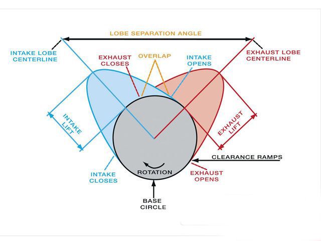
    As the camshaft rotates, for much of the rotation the cams are at "zero location".
    When the cam begins to become thicker, this is the "lift" beginning to take place.
    The amount of time the lobe(or cam) is creating lift, is called "duration"(measured in degrees of rotation of the crankshaft).

    The camshaft on the Chrysler 2.2/2.5 engines is an "over head" camshaft,
    and it is located over the cylinder head, attached to the cylinder head with "cam caps"(similar to crankshaft "main caps").

    The camshaft rotates by a toothed gear("cam gear") attached to the front,
    which a belt(timing belt) is attached to.
    This belt is also attached to a gear which is attached to the front of the crankshaft(crank gear).
    These 2 gears must be "timed" for proper valvetrain, and overall engine operation/performance.

    Below is an illustration of the operation of a valvetrain similar to our TM 8 Valve engine.
    (Camshaft and gear in green)


    .

  2. #242

    Re: TU and F4 Camshaft Follow-on Discussion

    Quote Originally Posted by knownenemy View Post
    Um, here ya go...


    Hope this helps to clear up this discussion a little.
    That is a great illustration, but begs the question. How do you locate the intake centerline of an asymmetric lobe? By x lift on either side of peak lobe lift? OR off of the @.050 lifter rise off both sides of the base circle? You could get two very different results, maybe up to 6 degrees. Click on illustration. You must know if the cam designer is referencing @.050 lifter rise method, or peak lift method of checking install "centerline" on the cam card.
    Most modern performance cam lobe profiles are asymmetric, and most cam cards (but not all) reference the center of the @.050 LIFTER RISE. duration. Hope that makes sense.
    Attached Thumbnails Attached Thumbnails Click image for larger version. 

Name:	asymmetric lobe profile.jpg 
Views:	268 
Size:	40.1 KB 
ID:	52069  
    Last edited by Warren Stramer; 11-13-2014 at 05:24 PM.
    best 1/8 ET-6.16 sec. best 1/8 speed-119.70 Best 1/4 MPH 145.5, Best 1/4 ET 9.65 sec. 8 valve NO NITROUS!!

  3. #243
    Garrett booster
    Join Date
    Nov 2009
    Location
    Sedalia
    Posts
    55

    Re: TU and F4 Camshaft Follow-on Discussion

    Quote Originally Posted by 168glhs1986 View Post
    Wait let's back up a little here.

    What is a camshaft and where is located?
    I really don't see the humor in this statement. Andy knows darn good and well what a camshaft is and where it is located. If you listen to what he is saying, you end up at the same place. The method he describes would get you where you want to be. Is it practical? NO. Is it possible, Yes. Why can't there be a discussion on here without the childish bull-crap? As far as I can tell Andy is correct in his thinking.

    Executing his idea is not very practical and not the method that I would use or recommend. With his machining knowledge could Asa do it?????? Yes. Would it be accurate? In my estimation, twice as accurate. Would it be hard to do? Yes.
    Last edited by shelbyvnt2; 11-13-2014 at 08:01 PM. Reason: sp.

  4. #244
    turbo addict moparzrule's Avatar
    Join Date
    Dec 2005
    Location
    Carlisle, PA
    Posts
    7,081

    Re: TU and F4 Camshaft Follow-on Discussion

    I like my cam's with 360 degrees of duration, then you know for sure you're flowing a lot of air. But I have a future design with 420 degrees of duration in the works. I call it the Type R, and it's guaranteed give you 100whp gains on an all stock engine. But if you have a cold air intake, and a 2'' exhaust system with a 7'' chrome tip, it's guaranteed for 150whp gains. The secret to the huge gains is it's made from 105% pure carbon fiber. Price will be 1 million pounds, payment in full up front. I only accept gold bullion as payment. Limited quantities available!
    Last edited by moparzrule; 11-13-2014 at 06:05 PM.

  5. #245
    Hybrid booster
    Join Date
    Mar 2013
    Location
    Trucksville, PA
    Posts
    481

    Re: TU and F4 Camshaft Follow-on Discussion

    Quote Originally Posted by Warren Stramer View Post
    That is a great illustration, but begs the question. How do you locate the intake centerline of an asymmetric lobe? By x lift on either side of peak lobe lift? OR off of the @.050 lifter rise off both sides of the base circle? You could get two very different results, maybe up to 6 degrees. Click on illustration. You must know if the cam designer is referencing @.050 lifter rise method, or peak lift method of checking install "centerline" on the cam card.
    Most modern performance cam lobe profiles are asymmetric, and most cam cards (but not all) reference the center of the @.050 LIFTER RISE. duration. Hope that makes sense.
    Yeah, I posted the illustration more for the terminology definitions
    than the actual carrying out of the degreeing.

    Here's a link to an accurate outline of degreeing camshafts
    (symetric, or the more common in TODAYS engines, asymmetric)

    http://www.cranecams.com/uploads/instructions/803_.pdf

  6. #246
    turbo addict
    Join Date
    Mar 2014
    Location
    Toronto Canada
    Posts
    1,772

    Re: TU and F4 Camshaft Follow-on Discussion

    a little off topic but worth the watchin'

    this could make cams as old school as stone wheels on wooden axles

    https://www.youtube.com/watch?v=Bch5B23_pu0#t=490

    you may have to restart the vid as I get only the ending everytime I click the link

  7. #247
    turbo addict
    Join Date
    Oct 2007
    Location
    Rockville, Md
    Posts
    3,522

    Re: TU and F4 Camshaft Follow-on Discussion

    Quote Originally Posted by shelbyvnt2 View Post
    I really don't see the humor in this statement. Andy knows darn good and well what a camshaft is and where it is located. If you listen to what is saying, you end up at the same place. The method he describes would get you where you want to be. Is it practical? NO. Is it possible, Yes. Why can't there be a discussion on here without the childish bull-crap? As far as I can tell Andy is correct in his thinking.

    Executing his idea is not very practical and not the method that I would use or recommend. With his machining knowledge could Andy do it?????? Yes. Would it be accurate? In my estimation, twice as accurate. Would it be hard to do? Yes.
    Who is Andy and I (Mike) will interject dumb and dry humorous comments from time to time. Call it a reset button.

    Seriously thou camshafts are confusing (obviously from this thread) and I needed a great explanation which Knownemeny so kindly provided.

    Thanks

  8. #248
    Garrett booster
    Join Date
    Nov 2009
    Location
    Sedalia
    Posts
    55

    Re: TU and F4 Camshaft Follow-on Discussion

    Quote Originally Posted by 168glhs1986 View Post
    Who is Andy and I (Mike) will interject dumb and dry humorous comments from time to time. Call it a reset button.

    Seriously thou camshafts are confusing (obviously from this thread) and I needed a great explanation which Knownemeny so kindly provided.

    Thanks
    Mike, I meant ASA, not Andy, sorry for my spelling. I follow these threads to try to learn about things that I am not real knowledgeable about. All of the, as Simon would say "This catiness and backstabbing shitt has got to stop. What are we? 3? Time for everyone to grow up, I've been here for 9 years and somethings never change, how sad. Why don't we pull the knives out of said backs and just concentrate on building fast cars/vans without the drama. Bad enough we have members slamming Gary D! TD is still taking shots at TM but I haven't seen any on here for awhile, at least that's a start.
    "
    Needs to stop. It is non-productive and only detracts from the topic. I am pretty sure you know what a camshaft is and where it is located. Set an example for others to follow. I am not trying to pick on you, I don't know you. There are several people in this thread that seem to have personal issues with each other that are cluttering up the discussion, now I am one of them!!!!!!!!!!!!!!!!

  9. #249
    Hybrid booster
    Join Date
    Dec 2005
    Location
    Bristol, CT
    Posts
    475

    Re: TU and F4 Camshaft Follow-on Discussion

    Quote Originally Posted by 168glhs1986 View Post
    Who is Andy and I (Mike) will interject dumb and dry humorous comments from time to time. Call it a reset button.

    I did find your comment lighthearted and comical! I guess one needs a sense of humor to get it.


    Carry on.

  10. #250
    Hybrid booster
    Join Date
    Mar 2013
    Location
    Trucksville, PA
    Posts
    481

    Re: TU and F4 Camshaft Follow-on Discussion

    I dig the occasional funny plug. They're what keep discussions real.
    However, there are those who have issues with reading things that differ from what they thought they knew.
    Or reading something that may be missing any molecule of information.
    And then they begin to take things personally, and post personal insults toward others.
    Seeing the posts as signs of weakness or ignorance,
    and viewing this as their opportunity to show how great they are.

    When I joined the forum, I understood that it is a place to find input on things.
    A place to hear the opinions of other members.
    Members who are free to voice anything they like(within the guide lines).

    The most important thing to me in this forum(and any other forum for that matter),
    is to be of assistance to newcomers. Not only newcomers to the forum,
    but newcomers to automotive diagnostics and repair.


    Whatever anyone is planning to say, my advise is this:
    Check the motives for which you are about to speak, prior to speaking.
    If the words you're about to type come from a place of anything but the welfare of others,
    maybe it shouldn't be said.

    But, that's just my 2 cents.
    Have a great night everyone.

  11. #251
    Moderator Turbo Mopar Staff Vigo's Avatar
    Join Date
    Feb 2006
    Location
    San Antonio,TX
    Posts
    10,798

    Re: TU and F4 Camshaft Follow-on Discussion

    Enjoying this thread.

    I like the innately cynical base assumption we are working off: That most cam grinders are incompetent.
    For the record, i dont find that hard to believe!

    When you start to think about how useless reference marks are unless you've verified them on an engine stand with a dial indicator, it starts to make sense that hardly anyone in this community can make anything run worth a ----. WHAT IF the keyway in the cam was cut off center AND one or more of the lobes were several degrees off AND one of the rod journals was ground a few degrees offset AND the bolt pattern wasnt drilled exactly right in the end of the crank OR the flywheel AND the timing mark on the flywheel was not properly referenced to the bolt pattern AND the timing marks in the bellhousing window were not properly spaced AND the ignition rotor you bought had its keyway improperly cast AND the cam gear arrows were rotated from where its keyway was cut AND AND AND AND AND EVERYONE WAS WRONG AND EVERYTHING IS BAD!

    So much tolerance stack up i just want to kill myself!

    DIAL INDICATORS AND DEGREE WHEELS FOR EVERYONE TO CHECK EVERYTHING!


    Dont push the red button.You hear me?

  12. #252
    Hybrid booster
    Join Date
    Sep 2011
    Location
    Maryland
    Posts
    345

    Re: TU and F4 Camshaft Follow-on Discussion

    What if the degree wheel isn't printed correctly?

  13. #253
    Moderator Turbo Mopar Staff Vigo's Avatar
    Join Date
    Feb 2006
    Location
    San Antonio,TX
    Posts
    10,798

    Re: TU and F4 Camshaft Follow-on Discussion


    Dont push the red button.You hear me?

  14. #254
    We Todd D dot D Turbo Mopar Staff sdac guy's Avatar
    Join Date
    Dec 2005
    Location
    Near Detroit MI
    Posts
    4,576

    Re: TU and F4 Camshaft Follow-on Discussion

    Now THAT is funny!


    Barry
    86 Shelby Lancer Prototype
    90 Daytona Shelby VNT
    91 Spirit R/T


    For your questions about SDAC, please contact BadAssPerformance


  15. #255
    Supporting Member II Turbo Mopar Contributor Shadow's Avatar
    Join Date
    Dec 2006
    Location
    Aubigny, Manitoba, Canada
    Posts
    5,088

    Re: TU and F4 Camshaft Follow-on Discussion

    Quote Originally Posted by acannell View Post
    So if I set the crank to TDC, drop the camshaft in, use a dial indicator to locate a lobe/valve centerline, and then rotate the camshaft 1/2 the degrees the cam card says to, the cam and crank wont be synchronized as intended?
    Well, thanks to this discussion, I actually Performed this procedure in my Dreams last night! lol The Funniest part........IT WORKED!!!!!!!!!!!

    Now, there Were a # of steps Missing in action, Prob the reason my Lizard brain didn't see it before.

    For some reason I was hearing Asa separating the cam from the crank (no timing belt connecting them till cam and crank are where you want them, Then attach the belt) Don't know why I thought this or where it came from, but it was throwing a wrench.

    Next, there was No explanation of how to reference the "imagined" marks on the cam gear to anything that would make it "relative".

    Anyways, here's what I did last night to the motor currently sitting on a stand in my shop. (While I was sleeping )

    1. I bolted the crank pulley onto the crank so that it would give a More accurate "degree" point that just marking dots on the crank Gear. (gear is too small for anything accurate, which is why the Degree wheel in the first place) I want to see someone try and mark all those degrees accurately on the crank gear! lol

    2. Located TDC on the Crank AND installed a Pointer to give an Accurate FIXED location for TDC.

    3. Installed the Degree wheel on cam AND installed a pointer to give a FIXED location for the cam position.

    So lack of Pointers to give a FIXED position were the first "missing" pieces of the puzzle and AFAICT you NEED BOTH!

    Also, Timing Belt Remains connected through whole process.

    4. Carry out the procedure for finding cam center using dial indicator,degree wheel on cam and pointer to reference locations till you have a degree chosen Indicating cam Centerline.

    5. Match cam position with TDC of crank......Done! (Did I miss anything?)

    So, my Apologies to Asa! This Can work with the few Extra detailed steps that I "Dreamt up". But it would take TWO pointers vs ONE.

    Thinking about it some more, you wouldn't even Need the degree wheel on the cam gear as long as you had an accurate Pointer and could make Accurate marks

    Robert Mclellan
    http://www.youtube.com/watch?v=wambNdfnu5M
    10.04 @ 143.28mph (144.82 highest mph)
    Worlds fastest 8v MTX Shelby Charger
    Manitoba's Fastest 4cyl!
    8 valve, No Nitrous!
    New clutch combo is the SH!T!

  16. #256
    We Todd D dot D Turbo Mopar Staff sdac guy's Avatar
    Join Date
    Dec 2005
    Location
    Near Detroit MI
    Posts
    4,576

    Re: TU and F4 Camshaft Follow-on Discussion

    Quote Originally Posted by Shadow View Post
    Anyways, here's what I did last night to the motor currently sitting on a stand in my shop. (While I was sleeping )

    1. I bolted the crank pulley onto the crank so that it would give a More accurate "degree" point that just marking dots on the crank Gear. (gear is too small for anything accurate, which is why the Degree wheel in the first place) I want to see someone try and mark all those degrees accurately on the crank gear! lol

    2. Located TDC on the Crank AND installed a Pointer to give an Accurate FIXED location for TDC.

    3. Installed the Degree wheel on cam AND installed a pointer to give a FIXED location for the cam position.
    How do you set the cam degree wheel to a position that represents a reference point on the cam? For example if you want 0 degrees to represent the top of #1 intake lobe (the probable centerline) how do you do it? Do you just eyeball it? How can you do this accurately? What is the fixed point of reference on the cam?


    Quote Originally Posted by Shadow
    4. Carry out the procedure for finding cam center using dial indicator,degree wheel on cam and pointer to reference locations till you have a degree chosen Indicating cam Centerline.
    Could you be a little more specific, exactly outlining this process. After all, the timing belt is on. Assuming you have found a way to accurately associate the cam and it's degree wheel, do you just find the point of max lift on the valve? Remember, this method is to be used instead of the engine book method, so you can't take readings at, say, .025" lift before and after max lift to find the centerline, because then that would be the "book" method.


    Quote Originally Posted by Shadow
    5. Match cam position with TDC of crank......Done! (Did I miss anything?)
    Yeah, you missed a lot. How exactly do you do this? For example, we are trying to install to an intake centerline of 112 degrees. So so when you have the engine at TDC, you are going to need to turn the cam (and only the cam) 56 degrees from the degree wheel indicated centerline (as ASA said, "turn the cam halfway ...").

    In order to turn the cam (on an adjustable sprocket), you will most likely need to remove the degree wheel from the sprocket to access the sprocket bolts. Now your cam placement reference is lost. How do you know how far to turn it? And you can't put the degree wheel back on, because you need to put a wrench on the cam bolt to turn it. Remember, you're fighting valve spring pressure on the #1 intake valve, so you can't turn the cam by hand.

    ASA's method is an approximation at best.


    Barry
    86 Shelby Lancer Prototype
    90 Daytona Shelby VNT
    91 Spirit R/T


    For your questions about SDAC, please contact BadAssPerformance


  17. #257
    Supporting Member II Turbo Mopar Contributor Shadow's Avatar
    Join Date
    Dec 2006
    Location
    Aubigny, Manitoba, Canada
    Posts
    5,088

    Re: TU and F4 Camshaft Follow-on Discussion

    Quote Originally Posted by sdac guy View Post
    How do you set the cam degree wheel to a position that represents a reference point on the cam? For example if you want 0 degrees to represent the top of #1 intake lobe (the probable centerline) how do you do it? Do you just eyeball it? How can you do this accurately? What is the fixed point of reference on the cam?
    The POINTER! THIS is what was missing in the conversation that threw me. As soon as you have a Pointer in a FIXED location, pointing at the cam gear, you can set a reference point........Make sense?

    Quote Originally Posted by sdac guy View Post
    Could you be a little more specific, exactly outlining this process. After all, the timing belt is on. Assuming you have found a way to accurately associate the cam and it's degree wheel, do you just find the point of max lift on the valve? Remember, this method is to be used instead of the engine book method, so you can't take readings at, say, .025" lift before and after max lift to find the centerline, because then that would be the "book" method.
    Negative, Asa said he would Use the dial indicator to find opening/ closing point just the Same as the book does. (or at least that's how I read it Now) IF you Are Not using a dial indicator on the valve to do this, then I would agree with what I previously stated, NOT HAPPENING! (not accurately anyways)

    Quote Originally Posted by sdac guy View Post
    Yeah, you missed a lot. How exactly do you do this? For example, we are trying to install to an intake centerline of 112 degrees. So so when you have the engine at TDC, you are going to need to turn the cam (and only the cam) 56 degrees from the degree wheel indicated centerline (as ASA said, "turn the cam halfway ...").

    In order to turn the cam (on an adjustable sprocket), you will most likely need to remove the degree wheel from the sprocket to access the sprocket bolts. Now your cam placement reference is lost. How do you know how far to turn it? And you can't put the degree wheel back on, because you need to put a wrench on the cam bolt to turn it. Remember, you're fighting valve spring pressure on the #1 intake valve, so you can't turn the cam by hand.

    ASA's method is an approximation at best.


    Barry
    Once you have Both marks Clearly Defined, moving the cam gear remains Exactly what it would be using the "Book" method. The only difference is you would need to calculate what the cam location is, Relative to the Crank @ TDC instead of @ 112deg. (this is where the degree wheel and pointer on the cam would come in) So Maybe you Would Need the degree wheel after all?

    Robert Mclellan
    http://www.youtube.com/watch?v=wambNdfnu5M
    10.04 @ 143.28mph (144.82 highest mph)
    Worlds fastest 8v MTX Shelby Charger
    Manitoba's Fastest 4cyl!
    8 valve, No Nitrous!
    New clutch combo is the SH!T!

  18. #258
    Hybrid booster
    Join Date
    Jul 2006
    Location
    Notre-Dame de L'Ile Perrot, QC
    Posts
    716

    Re: TU and F4 Camshaft Follow-on Discussion

    Is it beer thirty yet?

  19. #259
    We Todd D dot D Turbo Mopar Staff sdac guy's Avatar
    Join Date
    Dec 2005
    Location
    Near Detroit MI
    Posts
    4,576

    Re: TU and F4 Camshaft Follow-on Discussion

    Quote Originally Posted by Shadow View Post
    The POINTER! THIS is what was missing in the conversation that threw me. As soon as you have a Pointer in a FIXED location, pointing at the cam gear, you can set a reference point........Make sense?
    So the degree wheel doesn't synchronize with any particular point on the cam, it is just installed as a reference point?

    Quote Originally Posted by Shadow
    Negative, Asa said he would Use the dial indicator to find opening/ closing point just the Same as the book does. (or at least that's how I read it Now) IF you Are Not using a dial indicator on the valve to do this, then I would agree with what I previously stated, NOT HAPPENING! (not accurately anyways)
    I just looked through the thread again and I can't find where he said or implied that. From what I read he was going to use the max lift as the centerline, but he doesn't really say. He glosses over many details and that is why I started trying to nail down exactly HOW he would accomplish this.


    Quote Originally Posted by Shadow
    Once you have Both marks Clearly Defined, moving the cam gear remains Exactly what it would be using the "Book" method. The only difference is you would need to calculate what the cam location is, Relative to the Crank @ TDC instead of @ 112deg. (this is where the degree wheel and pointer on the cam would come in) So Maybe you Would Need the degree wheel after all?
    Again, he states it simply as,
    Quote Originally Posted by acannell
    So if I set the crank to TDC, drop the camshaft in, use a dial indicator to locate a lobe/valve centerline, and then rotate the camshaft 1/2 the degrees the cam card says to, the cam and crank wont be synchronized as intended?
    And in the example I gave, using a cam centerline of 112 degrees, half of that value would be 56 degrees. So his method sounds good in theory and would work.

    But I don't see how to accomplish it. In order to loosen the bolts (so the cam can be turned) the cam degree wheel must be removed. And with a wrench on the cam bolt, it can't be put back until the cam is turned to the proper place and the bolts tightened again. So, how do you know how far to turn the cam? Without the degree wheel on the cam, there is no reference.

    Add to that the fact that there is valve spring pressure acting on the lobe, because the valve maybe somewhat or fully open. What is to keep the cam from snapping into a "relaxed" position as soon as the sprocket bolts are loosened?

    His method sounds good when it is stated in very broad simple terms (as he is apt to do). But when we start to go through all the actual steps required, thinking through what would happen or need to happen at each stage, then his procedure breaks down, and proves impossible to do.

    Barry
    86 Shelby Lancer Prototype
    90 Daytona Shelby VNT
    91 Spirit R/T


    For your questions about SDAC, please contact BadAssPerformance


  20. #260
    turbo addict
    Join Date
    Mar 2014
    Location
    Toronto Canada
    Posts
    1,772

    Re: TU and F4 Camshaft Follow-on Discussion

    if , if the cam has the threaded hole at the back end where the air pump pulley would have gone one could install the degree wheel at the back end of the head so it's not in the way of the belt and pulley at the front

    I think I may be permenantly cross eyed from reading this thread - good thing I have a late edition of the 2.2 book AND the degreeing instructions on the back of my d/c degree wheel

    I loned the wheel and tools to a local here last year when I sold him a multy slot pulley
    he said it took a few tries to figure out what the hell he was doing so I take from that , the best way of learning this is with the tools in hand and actually doing it

    anything else , is only conjecture and confusion

Similar Threads

  1. Finally got around to it...some follow up questions
    By 89FerrariShelby in forum Maintenance & General Tech
    Replies: 5
    Last Post: 08-16-2010, 08:15 PM
  2. Follow the tubes!
    By 8valves in forum Exhaust
    Replies: 22
    Last Post: 07-30-2007, 07:04 AM
  3. 86/87 GLHS fan assembly differences (follow on pix)
    By Marcus86GLHS in forum Shelby Models - Whittier Factory Cars
    Replies: 0
    Last Post: 01-23-2007, 10:14 AM

Tags for this Thread

Posting Permissions

  • You may not post new threads
  • You may not post replies
  • You may not post attachments
  • You may not edit your posts
  •