Page 1 of 2 12 LastLast
Results 1 to 20 of 32

Thread: Building SMEC harness for GLHS. Trouble with a few pins...

  1. #1
    Hybrid booster
    Join Date
    Mar 2013
    Location
    Trucksville, PA
    Posts
    481

    Question Building SMEC harness for GLHS. Trouble with a few pins...

    Here are two posts from the other forum I haven't received replies to yet:

    First; I have both the 1987 and 1989 FSMs.
    I also have the troubleshooting supplement manual with the big diagram.
    The SMEC & harness I have are from an 89' Shelby Daytona 2.2T2.
    (Please hold the "should've used a van harness" comments please; thank you. lol)
    The 40 pin bulkhead connector is for an 87' GLHS("L" body 2dr), 5-spd, T2.

    What I've been coming across is that some of the "names" of components,
    or controlled systems had changed.
    This makes some of this swap somewhat challenging.

    Also, I'm deleting the Fuse-links from the harness and installing a PDC.
    (Hence the longer Daytona harness)
    But at this point, I'm interested only in the details of the bulkhead connector swap.

    For example; In the 1989 SMEC 50 pin bulkhead connector there is a wire listed as "Battery Feed";
    But in the 1987 40 pin bulkhead connector, there is no such wire.
    (This is just one example; there are more, but I'll have to note them specifically,
    and return with my findings)
    .

    This task is beginning to appear as though I may be better off building the entire harness myself.
    This thought comes from the amount of wires that seem to be left un-used in the later harness.
    (And, anyone who knows me, knows that I just CAN'T leave un-used wires in there; weight is my sworn enemy)

    Also, when I finish the harness, I intend to start another thread titled,
    "LM/PM to SMEC wiring harness"(or something like that); this will include all of the changes,
    and clear-cut direction on exactly where they go.

    But, in the mean-time, anyone who might have a few pointers for me is welcome to chime in here.
    If you've done this swap, and have a diagram, that would be ab-SOL-utely awesome!

    The next day:
    This morning, I went out and noted the pins I'm having trouble with.

    They are as follows:
    "G" 50-pin connector(From 89' FSM)
    Pin #1 --- Battery Feed -------------- 12RD
    Pin #43 --- Ignition Switch ----------- 20BK/RD
    Pin #47 --- Splice Ignition Run Circuit - 14DB
    Ignition Switch ------------------------- 14DB
    (Pin #47 has 2 wires)
    Pin #49 --- Ignition Switch ----------- 14PK
    Pin #50 --- Ignition Switch ------------12BK/OR

    In the 87' FSM, the "L" body bulkhead connector lists only 3 Ignition related pins:
    Pin #1 --- Ignition Switch -------------- 12PK
    Pin #14 --- Starter Relay Ignition --------- 18YL
    Pin #38 --- Splice Ignition Run Circuit --- 14DB
    -------------------------------------------- 14DB
    (Pin #38 has 2 wires)
    Pin #40 --- Ignition Switch ------------- 12RD

    The questions still remain for me.
    Maybe I'm missing something obvious.
    At this point, I'll begin to trace the diagram,
    and then physically check the harness for where the wires go.
    I should be able to do this with relative ease.
    However, if another member has done this and has a diagram,
    that would make things quite a bit simpler.

    Note: I will edit in the pin-out for the "L" body as per the 89' FSM in a moment.

    EDIT:
    Ok, the 89' FSM lists 5 pins for the "L" body which are Ignition related;
    Pin #1 --- Battery Feed ------------------ 12RD
    Pin #31 --- Starter Relay Ignition -------14YL
    Pin #47 --- Splice Ignition Run Circuit --- 14DB
    Pin #49 --- Ignition Switch --------------- 12RD
    Pin #50 --- Ignition Switch --------------- 12PK

    Following either the "G" body OR the "L" body Bulkhead pin-out,
    I'm having trouble distinguishing what goes where.
    Any help would be very much appreciated.

    Thank again folks!

  2. #2
    Rhymes with tortoise. Turbo Mopar Staff cordes's Avatar
    Join Date
    Dec 2005
    Location
    Tuscola, IL
    Posts
    21,460

    Re: Building SMEC harness for GLHS. Trouble with a few pins...

    You need to be looking at the circuit names. Z1, J1, J2, etc. Compare those between the two sets of diagrams and then report back. I'm willing to bet that you'll be out of problems by that time.

  3. #3
    Hybrid booster
    Join Date
    Mar 2013
    Location
    Trucksville, PA
    Posts
    481

    Re: Building SMEC harness for GLHS. Trouble with a few pins...

    Quote Originally Posted by cordes View Post
    You need to be looking at the circuit names. Z1, J1, J2, etc. Compare those between the two sets of diagrams and then report back. I'm willing to bet that you'll be out of problems by that time.
    Seems to make sense, but the 87' FSM lists "J" circuits,
    and the 89' has no such letter in the bulkhead pin-out.

  4. #4
    Rhymes with tortoise. Turbo Mopar Staff cordes's Avatar
    Join Date
    Dec 2005
    Location
    Tuscola, IL
    Posts
    21,460

    Re: Building SMEC harness for GLHS. Trouble with a few pins...

    Quote Originally Posted by knownenemy View Post
    Seems to make sense, but the 87' FSM lists "J" circuits,
    and the 89' has no such letter in the bulkhead pin-out.
    There should be at least a J2 circuit which is the DB wire going back to the ign switch. IIRC the J1 circuit is a red wire. I'm finishing up an 86 NA GLH to 90 SBEC wiring conversion. Look at the actual diagrams if you get stuck and you can trace them to where they should go. I'm intimately familiar with my 90 manual by this point.

  5. #5
    Hybrid booster
    Join Date
    Mar 2013
    Location
    Trucksville, PA
    Posts
    481

    Re: Building SMEC harness for GLHS. Trouble with a few pins...

    Cordes, bro I'm sorry.
    There isn't a J in the bulkhead pin-out,
    but THERE IS a J1 pin in the 50 pin connector.
    I just followed it, and low and behold;
    As predicted, I think my issue may be solved.
    I'll keep you updated.

    BTW; You're going to end up being responsible for a few different parts of this build.
    I'll be using your a555 build YouTube vids as a guide when I do mine.

    Thanks my friend,
    Donnie

  6. #6
    Hybrid booster
    Join Date
    Mar 2013
    Location
    Trucksville, PA
    Posts
    481

    Re: Building SMEC harness for GLHS. Trouble with a few pins...

    Coming along well, but having trouble with one circuit.
    D4 WT/TN Brake sense.
    On the 50-way "G" body harness, this wire goes from the bulkhead to a 6 pin black connector.
    On the 40-way "L" body plug, it is pin #11 Brake Switch Signal, which goes to the LM.

    Anyone have any idea what the deal is with this particular circuit?
    cordes, where are you bro? lol

    Thank you, in advance.

  7. #7
    turbo addict
    Join Date
    Dec 2006
    Location
    MPLS, MN
    Posts
    3,590

    Re: Building SMEC harness for GLHS. Trouble with a few pins...

    I have a s-60 harness out of vehicle. Do you need me to run continuity checks between 40 pin and SMEC connectors? If so tell me what pin on bulkhead connector you need answers to.
    Todd

  8. #8
    Rhymes with tortoise. Turbo Mopar Staff cordes's Avatar
    Join Date
    Dec 2005
    Location
    Tuscola, IL
    Posts
    21,460

    Re: Building SMEC harness for GLHS. Trouble with a few pins...

    The wire probably goes from the black connector to the SMEC.

    - - - Updated - - -

    ETA: Check out Russ' site to help with some of this. In 89 they called it D40 it looks like.

    http://www.minimopar.net/ecu/smec-1988-t1.html

  9. #9
    turbo addict
    Join Date
    Mar 2014
    Location
    Toronto Canada
    Posts
    1,772

    Re: Building SMEC harness for GLHS. Trouble with a few pins...

    brake sence could be 1 of three things

    pressure switch on the prop valve
    low fluid warning if equiped with 21 way message center
    worn brake pads - with 21 way mess center

    the press switch wire should look like the one from your L body

    if it's going to some 6 way connector that seems not to have a mateing half my $$ is on one of the other two options

    IF you can trace it back through the bulkhead connectors for thr G body to the brakelight switch it might be the trigger wire to shut off cruise control

  10. #10
    Rhymes with tortoise. Turbo Mopar Staff cordes's Avatar
    Join Date
    Dec 2005
    Location
    Tuscola, IL
    Posts
    21,460

    Re: Building SMEC harness for GLHS. Trouble with a few pins...

    The brake sense wire comes out of the brake switch and goes to the ECU. That's how we can use it for boost control in our cars with the custom cals.

  11. #11
    Hybrid booster
    Join Date
    Mar 2013
    Location
    Trucksville, PA
    Posts
    481

    Re: Building SMEC harness for GLHS. Trouble with a few pins...

    Quote Originally Posted by 4 l-bodies View Post
    I have a s-60 harness out of vehicle. Do you need me to run continuity checks between 40 pin and SMEC connectors? If so tell me what pin on bulkhead connector you need answers to.
    Todd
    It's more of a question about where this wire leads to.
    Because at this point, from my 40-way into the "G" body harness, I'm good.
    But, the WT/TN wire goes from pin 11 to a 6-pin black plug,
    the wire comes out of this plug, and goes nowhere; it's cut off with the rest of the wires in the 6-pin.

    Quote Originally Posted by cordes View Post
    The wire probably goes from the black connector to the SMEC.

    - - - Updated - - -

    ETA: Check out Russ' site to help with some of this. In 89 they called it D40 it looks like.

    http://www.minimopar.net/ecu/smec-1988-t1.html
    Thanks cordes, but the SMEC & harness are from an '89 T2 Daytona.
    There's no WT/TN wire in the 60 way SMEC plug.
    http://www.minimopar.net/ecu/smec-1988-t2.html

    Quote Originally Posted by Dr. Johny Dodge View Post
    brake sence could be 1 of three things

    pressure switch on the prop valve
    low fluid warning if equiped with 21 way message center
    worn brake pads - with 21 way mess center

    the press switch wire should look like the one from your L body

    if it's going to some 6 way connector that seems not to have a mateing half my $$ is on one of the other two options

    IF you can trace it back through the bulkhead connectors for thr G body to the brakelight switch it might be the trigger wire to shut off cruise control
    Well, I guess it could be any of those 3.
    I have no clue what was in the car that the harness came from.
    All I do know is it's from a 1989 Shelby Daytona, 2.2T2, manual trans.
    This would lead me to believe that it most likely was equipped with all three of the choices you list.
    But, since it was cut off after this 6-pin plug,
    I would be inclined to think it lead to the cluster for a brake pad wear indicator lamp.
    The 6-pin connector is really clean, and before the firewall grommet.
    So, it's an interior connection, I think.

    Thanks a lot guys for the assistance.
    I have threads at both forums, and I'm kinda bouncing questions between the 2.
    but really, the best guys are responding.
    I'll get this figured, documented, and a new thread started for this particular job.
    This way, others may find it far simpler.

  12. #12
    Rhymes with tortoise. Turbo Mopar Staff cordes's Avatar
    Join Date
    Dec 2005
    Location
    Tuscola, IL
    Posts
    21,460

    Re: Building SMEC harness for GLHS. Trouble with a few pins...

    The brake sense wire from the LM should go to pin 29 on the SMEC. The wire on the brake prop valve only triggers the warning light. That would be the same thing to trigger a brake pad warning deal too. The brake sense is the brake pedal switch signal.

  13. #13
    turbo addict
    Join Date
    Mar 2014
    Location
    Toronto Canada
    Posts
    1,772

    Re: Building SMEC harness for GLHS. Trouble with a few pins...

    ok remember when I told you the brake light switch moved along the wireing to the engine side of the bulkhead connector as it was now under the dash ?

    and your L body brake light switch in on the dash side of the b-h connector

    so , it's the same thing + the spade connectors inside the b-h connector
    hope that helps some

  14. #14
    Hybrid booster
    Join Date
    Mar 2013
    Location
    Trucksville, PA
    Posts
    481

    Re: Building SMEC harness for GLHS. Trouble with a few pins...

    Here's the pin I'm referring to.
    Hopefully the pics will help clear it up a bit, based on the 6-pin plug.
    The Wt/TN wire goes into the 6-pin(from the 40-way),
    and comes out the other side of the 6-pin as a WT only wire.
    Maybe that'll also help. Sorry for omitting that info thus far;
    I hadn't even noticed it myself til' this morning.lol


    ^Also, for what it may be worth, the 2 YL/RD wires in the 6-pin(both in same pin), one of them leads directly to the 3-pin connector in the pic.


    ^(although the wire in question appears to be gray in the pic, rest assured, it's white/tan before the 6-pin, and white only after the 6-pin)

    Thanks again guys.

  15. #15
    Rhymes with tortoise. Turbo Mopar Staff cordes's Avatar
    Join Date
    Dec 2005
    Location
    Tuscola, IL
    Posts
    21,460

    Re: Building SMEC harness for GLHS. Trouble with a few pins...

    Check your diagrams and look at the brake switch and cruise. If you look up the cavity that the wire comes from on the SMEC you'll probably know just what sheet to look at.

  16. #16
    Hybrid booster
    Join Date
    Mar 2013
    Location
    Trucksville, PA
    Posts
    481

    Re: Building SMEC harness for GLHS. Trouble with a few pins...

    Quote Originally Posted by cordes View Post
    Check your diagrams and look at the brake switch and cruise. If you look up the cavity that the wire comes from on the SMEC you'll probably know just what sheet to look at.
    Yessir; I traced these wires in the 6-pin,
    and it appears to be something to do with the cruise system.
    I have no intentions of using cruise.
    So, OK to simply delete this?
    Or is this signal used for additional features and driveability functions?

  17. #17
    Hybrid booster
    Join Date
    Mar 2013
    Location
    Trucksville, PA
    Posts
    481

    Re: Building SMEC harness for GLHS. Trouble with a few pins...

    OK, double checked all of my connections,
    and that WT/TN wire from #11 in the 40-pin BH connector is the only question that remains.
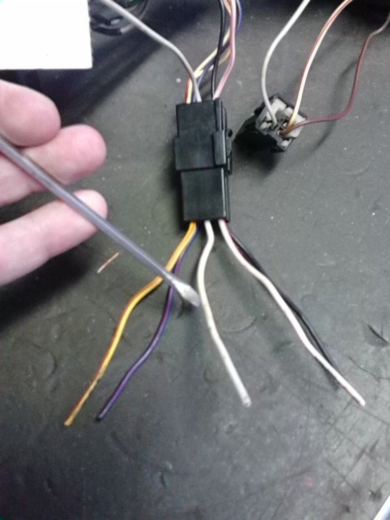
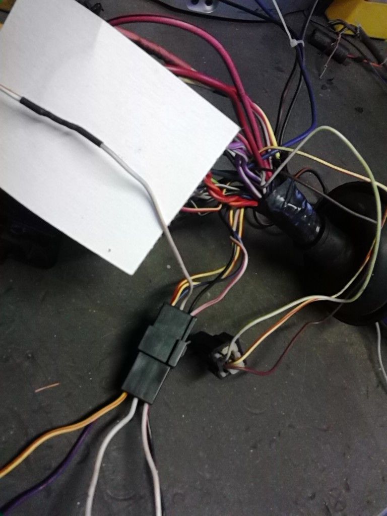
    Actually, that entire 6-pin black plug that goes under the dash is the question.

    Here's the diagram I've typed for this:
    ‘87 2.2 T2 LM/PM 40pin Bulkhead to ‘89 2.2 T2 50pin SMEC harness
    Notes: (*) = wire not in 50-pin connector
    (X2) = two wires in same pin
    Note pin #32 in 40-pin connector; Simply delete one of the 2 DG/BK wires.
    1987 40-pin connector_________________________________________ __________________________________________________ ____________1989 50-pin connector
    (engine compartment side of connector)________________________________________ _________________________________(pin# reference for which wire in harness)
    Pin #-Circuit-Color --- Description------------------------------------ Connect to ---- Pin# --- Circuit ------------------ Description-----------------
    #1 - Not Used
    #2 - Not Used
    #3 - Not Used
    #4 - J10-12PK---Ignition Switch ----------------------------------------- To ---------- (*) -12PK/BK--------------In Starter Harness Plug
    #5 - L3-16RD(X2)-Left High Beam ----------------------------------------- To -----------#6 - L3-14RD/OR(X2)-----Headlamp High Beam
    ______________________Right High Beam
    #6 - L1-12BK---Splice Charging Circuit Alternator ------------------------- To -----------#1 - L1-12RD-------------Battery Feed
    #7 - B1 - 12WT---Back Up Lamp Switch ----------------------------------To -----------#27 - B1 -18WT----------Back Up Lamp Switch
    #8 - B2 - 18VT/BK---Back Up Lamp Switch--------------------------------To------------#28 - B2- 18VT/BK------ Back Up Lamp Switch
    __________________Neutral Start and Back Up lamp Switch
    #9 - U3 - 20OR/LG---Fuel Pacer Lamp-------------------------------------To---- None: Delete wire from 40-pin
    #10 - K3 - 20BK/OR---Power Loss Light Ground----------------------------To -----------#38 - K3 - 20BK/PK------ Check Engine Lamp

    #11 - D4 - WT/TN---Brake Switch Signal---To---6-pin harness 18WT/PK(Remove WT/PK wire from 6-pin, solder to WT/TN wire; 6-pin other wiring is deleted)

    #12 - C2 - 16DB/YL---A/C Low Pressure Switch----------------------------To-----------#37 - C20-18DB/OR--A/C Damped pressure Switch
    #13 - D6 - 18LG---Left turn Signal----------------------------------------To-----------#21 - D6-18LG-------------Left Turn Signal Lamp
    #14 - S2 - 18YL---Starter Relay-Ignition----------------------------------To-----------(*)- S2-14YL/BK---------In Starter Harness Plug
    #15 - V3 - 18BR---Winshield Wiper Motor----------------------------------To-----------#45 - V3-18BR------------Windshield Wiper Motor
    #16 - V4 - 18RD---Windshield Wiper Motor--------------------------------To-----------#46 - V4-18RD-------------Windshield Wiper Motor
    #17 - G2 - 20VT--Water temperature Gauge or Lamp-----------------------To-----------#17 - G20-VT/YL-Water temperature Sending Unit
    #18 - G6 - 20GY---Oil Pressure Switch------------------------------------To-----------#18 - G6-20GY-------------Oil pressure Switch
    #19 - V5 - 18DG---Windshield Wiper Motor--------------------------------To-----------#35 - V5-18DG-----------Windshield Wiper Motor
    #20 - V1 - 18DB----Windshield Wiper Motor-------------------------------To------------#36 - V6-18DB------------Windshield Wiper Motor
    #21 - H2 - 18DG/RD---Horn----------------------------------------------To------------#32 - H2-14DG/RD-------Horn
    #22 - Not Used
    #23 - Not Used
    #24 - L7 - 18BK/YL(X2)-Right Park & Side marker Lamps--------------------To-----------#26 - L7-18BK/YL(X2)---Splice Side Marker and Park and
    _____________________Left Park & Side Marker Lamps___________________________________________Tu rn Signal lamps
    #25 - A3 - 14PK-----Battery-Hazard Flasher-------------------------------To-----------#23 - A3-16PK/WT---Battery-Hazard Flasher
    #26 - Not Used
    #27 - G60 - 20GY/YL---Oil Pressure Sending Unit--------------------------To------------#19 - G60-20GY/YL---Oil Pressure Sending Unit
    #28 - Not Used
    #29 - P5 - 20BK---Brake Warning lamp Switch-----------------------------To------------#34 - P5-20GY/BK--Brake Warning Lamp Switch
    #30 - Not Used
    #31 - T21 - 20GY/LB----Tachometer--------------------------------------To-----------#33 - T21-20GY/LB--------Tachometer
    #32(See notes) - Z1 - 14DG/BK(X2)--Fuel pump Feed--------------------To------------#24 - Z1-16DG/BK----------Fuel Pump Feed
    #33 - V10 - 20BR---Windshield Washer Motor------------------------------To-----------#29 - V10-18BR----Windshield Washer Motor
    #34 - D5 - 18TN-----Right Turn Signal-------------------------------------To-----------#22 - D5-18TN-------Right Turn Signal Lamp
    #35 - C13 - 12BK/RD--Electrically Heated rear Window---------------------To-----------#48 - C13-12BK/RD-Electrically Heated Rear Window
    #36 - Not Used
    #37 - Not Used
    #38 - J2 - 14DB(X2)----Splice Ignition Run Circuit--------------------------To----------#47 - J2-14DB(X2)------Splice Ignition Run Circuit
    _____________________Splice ignition Run Circuit___________________________________________ ________Ignition Switch
    #39 - L4 - 16VT(X2)----Right Headlamp Low Beam-------------------------To----------#35 - L4-14VT(X2)------Headlamp - Low Beam
    _____________________Left Headlamp Low Beam
    #40 - J1 - 12RD----Ignition Switch----------------------------------------To-----------(*) - J1-12RD------------In Starter Harness Plug

    This sheet should be printable for anyone building a SMEC for their pre-1988 "L" body.
    Best wishes with it.
    Last edited by knownenemy; 09-30-2014 at 12:28 PM.

  18. #18
    Rhymes with tortoise. Turbo Mopar Staff cordes's Avatar
    Join Date
    Dec 2005
    Location
    Tuscola, IL
    Posts
    21,460

    Re: Building SMEC harness for GLHS. Trouble with a few pins...

    The brake signal from the LM at pin 11 should go to the brake signal at the SMEC. I believe that's pin 29.

  19. #19
    Hybrid booster
    Join Date
    Mar 2013
    Location
    Trucksville, PA
    Posts
    481

    Re: Building SMEC harness for GLHS. Trouble with a few pins...

    Quote Originally Posted by cordes View Post
    The brake signal from the LM at pin 11 should go to the brake signal at the SMEC. I believe that's pin 29.
    Pin-29 is the P5 circuit.
    I'm believing more and more, that this little 6-pin black plug will be deleted.
    it's like cruise or trip or some hawty-tawty, upper class thing.lol
    DELETED!

    but, I'll leave it in the harness 'til I install, and start 'er up.
    If there's an issue, it'll be the first place I look.

    cordes, I really appreciate the help.
    Dr.Johny Dodge and 4 l-bodies, thank you for the effort and, offers as well.
    BTW: 4 l-bodies, what do you think about this pin-11, and additional 6-pin black plug?

  20. #20
    Rhymes with tortoise. Turbo Mopar Staff cordes's Avatar
    Join Date
    Dec 2005
    Location
    Tuscola, IL
    Posts
    21,460

    Re: Building SMEC harness for GLHS. Trouble with a few pins...

    Click image for larger version. 

Name:	DSCN2875[1].jpg 
Views:	184 
Size:	500.8 KB 
ID:	50504I'm sorry I thought you were talking about the pins coming off of the LM.

    I've got a copy of an 87 service manual. Here is a pic of the G body bulk head. Why does it say 50 way for the 87 and you have a 40 way? I thought the 40 way was out of the L body cars?

Page 1 of 2 12 LastLast

Similar Threads

  1. need help building injector harness!!!!
    By thewraith1971 in forum "I need help!"
    Replies: 20
    Last Post: 11-10-2011, 06:29 PM
  2. Building/fabricating a NEW engine harness.
    By 135sohc in forum Electrical & Fuel System
    Replies: 9
    Last Post: 05-27-2010, 02:22 PM
  3. Harness Connectors and Pins
    By zin in forum Electrical & Fuel System
    Replies: 3
    Last Post: 12-09-2007, 03:45 AM
  4. FS: Wiring harness, stock SMEC, TU SMEC, mirrors
    By supercrackerbox in forum Parts For Sale
    Replies: 7
    Last Post: 03-29-2007, 09:19 PM
  5. Smec Pins
    By show-off in forum Electrical & Fuel System
    Replies: 10
    Last Post: 12-24-2005, 12:41 PM

Tags for this Thread

Posting Permissions

  • You may not post new threads
  • You may not post replies
  • You may not post attachments
  • You may not edit your posts
  •