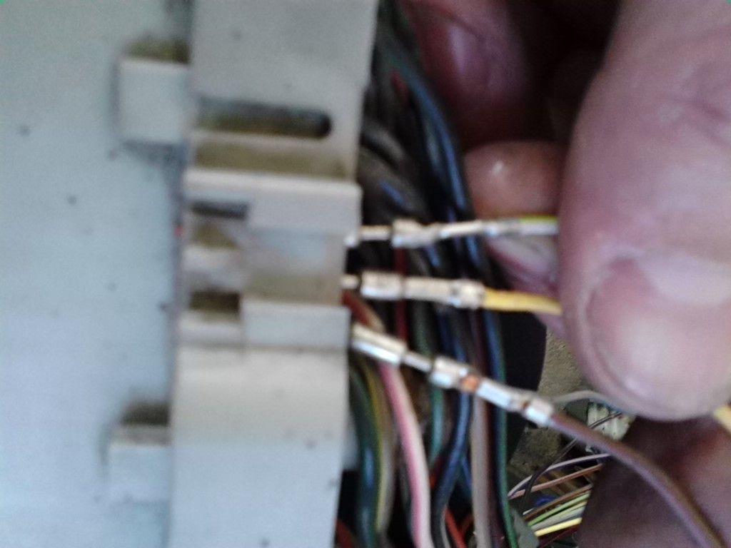
Eta: Here is the L body which is the harness I think you must have. It has the brake stuff at pin 11. It's for the turbo so that further tells me that it needs to go to the SMEC.
![Click image for larger version.
Name: DSCN2876[1].jpg
Views: 98
Size: 503.9 KB
ID: 50505](http://www.turbo-mopar.com/forums/attachment.php?s=dbc07bf1e2fb7e4b6814b0dec9bbaf69&attachmentid=50505&d=1402608321&thumb=1)


Eta: Here is the L body which is the harness I think you must have. It has the brake stuff at pin 11. It's for the turbo so that further tells me that it needs to go to the SMEC.
Haven't followed this thread real close but that looks like brake switch connector for sure. On a cruise control vehicle the brake switch has six wires. On a non-cruise vehicle the brake switch has only four wires. On both the cruise and non-cruise switch it has 2 white wires. One looks to be white with pink tracer and the other white wire looks to be all white. Both white wires terminate at brake switch. A yellow w/red and a blue w/red wires are added to cruise brake switch.Originally Posted by knownenemy

If this info is all dedundant as Glida would say, "nevermind" (lol).
Oh it just came to me while walking the dog, the white/tan wire is probably the independent 3rd brake light signal wire. That would be my best guess. I'll bet the 85 brake switch didn't have that wire.
Todd
Last edited by 4 l-bodies; 06-12-2014 at 11:07 PM. Reason: added info
I have the '87 FSM and '89 FSM here.
1988 and up "L" bodies were 50-way bulkhead connector.
The only reason I'm into the "G" body wiring is because that's where this harness is from.
The vehicle it's going in is a 1987 GLHS(2dr.)
That's what I thought as well at first,
but after following the wires physically and not seeing it in the harness or pin,
(This WT/TN wire isn't in the harness at all. Just from the bulkhead to this 6-pin connector)
I began searching the wiring diagrams one at a time.
I found this WT/TN wire, it goes from the brake switch to the 6-pin plug, and then changes to a solid white wire.
More investigating, and I'll know exactly what it's intended purpose is.
Not redundant(or dedundant. lol) at all.
At this point, I feel it's just a matter of tracing this circuit in the FSM,
documenting the entire path,
and completing the circuit if necessary.
If it's the high mount brake light, then I'll connect it,
but if it's the cruise, or some trip cpu signal, IT'S OUT! lol
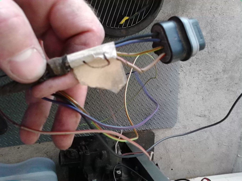
The harness in your pics appears to be it, but the PK wire isn't there.
May have been removed. But, all the others look the same.
I could see this being it. The seller I got the harness from may have just cut the wires at the brake switch.
BTW: If anyone takes a look at this thread, and has a 1989-90 Shelby Daytona interior harness laying around,
maybe you'd trace this wire and let me know what the heck it is.lol
(Remember, after the 6-pin black plug it's just solid WT wire)
Thanks again guys.
Sorry bout the typo. Missing pink wire on switch connector? That is power wire coming out of #6 fuse on 89 g-body according to 89 FSM. 89 FSM says that cyclops light wire is white w/tan (circuit D4). You will want to connect that white w/tan wire on on your vehicle as it splices upstream into 4 way flashers besides the cyclops brake light. Ties into one of center terminals on brake switch. The other center terminal is the pink power wire you are missing from the #6 fuse. That appears to be the power source for the cyclops light.
Todd
Last edited by 4 l-bodies; 06-14-2014 at 08:25 PM.
Now that sounds better.
Thanks a lot 4 l-bodies!
I'll have to track this circuit, and make any necessary repairs.
Apparently, it's a circuit needed for the '89 "G" SMEC harness?
The WT/TN wire in the "L" body 40-pin connector(#11)
now goes to this 6-pin connector.
So, where would it go to in my '87 "L" body? Since the interior harness is different...
But again, I'll get into both manuals, and get this entire circuit straightened out.
Honestly, none of this circuit was part of the '89 "G" 50-pin bulk head connector;
It was in the harness, but wires came through the grommet, and to the 6-pin rather than the 50-pin.
But in my '87 "L" body harness, there IS a WT/TN wire through the 40-pin Bulkhead.
This is a circuit I'll just have to get straightened out with patience and thoroughness.
It'll be fine, and after I've done it, no one else wil have to go through it like this again.
that follows with my description of them moveing the brakelight switch wireing past the 50 way , thus it's actually on the engine half of the wireing harness , wires through the b-h connector should be the brakelights - going to the rear (via the 25 way at the side of the dash)and the pressure warning to the cluster
have you tryed matching up the L body brake switch connector to this G body one with the wires your trying to trace ?
the wires that come from the connector you posted the pics of should be same / simular to whats comeing from the L body brake switch plug
the wire(s) going out through the gromit should be same / simular to what would run out the L body b-h connector , over the firewall and back in to the lm (or pm ?)
or off to run (shut off )cruise control
sorry top be vague - it's been a 20 years + since I did L body wireing
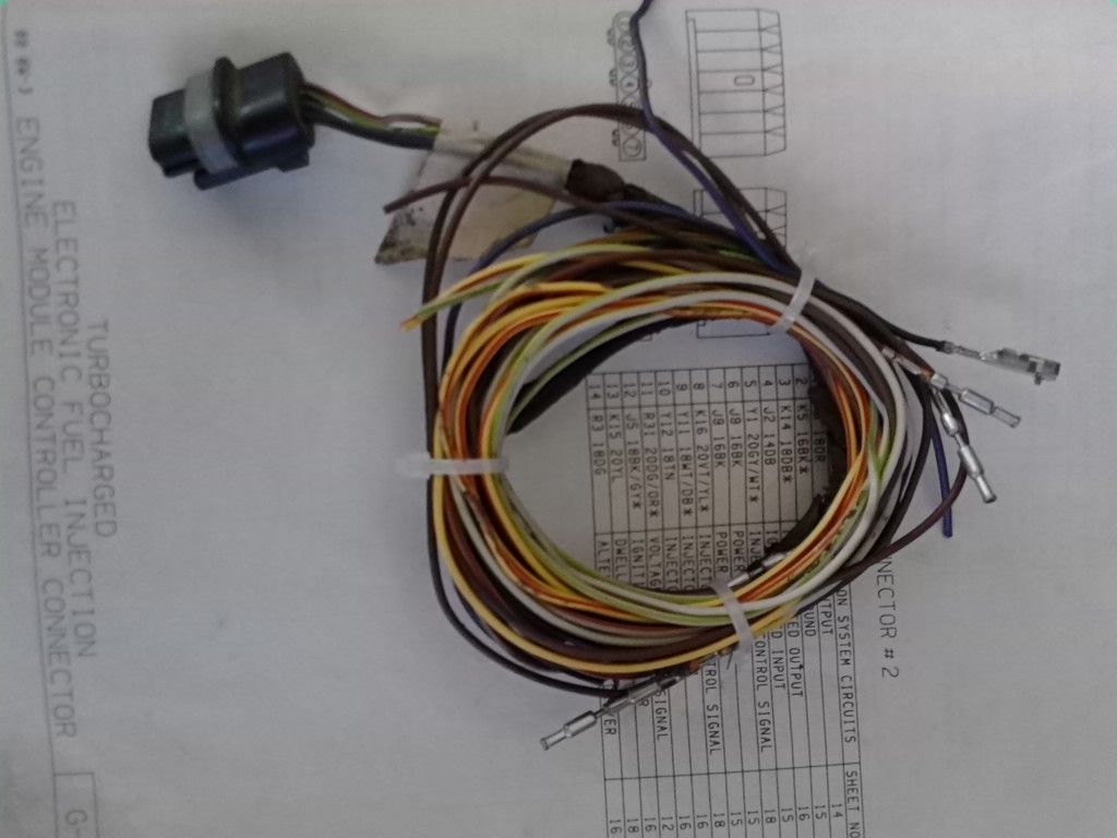
After tracing the 6-pin harness, I found it's installed on cars with cruise.
Every wire in the harness(save for the WT/PK) goes to the cruise module.
In the '89 FSM, it shows 2 different brake switches, and I have no cruise.
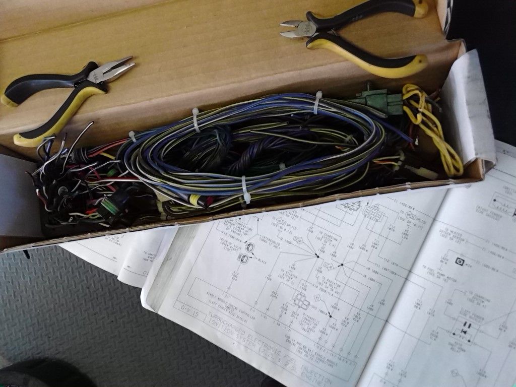
Traced every wire through the 60-pin harness,
and I was able to delete the un-necessary ones(Pretty much all of them).
The WT/PK wire is the wire that goes directly to the WT/TN wire in the '87 "L" body 40-pin bulkhead(pin #11).
Deleted pins 7, 8, 9, and 60 along with the wires from the 60-pin SMEC connector.
Found the cruise control plug, and deleted it along with its wiring
A while back, when I decided to go SMEC, another member had told me,
"There's going to be a lot of wires not used, so be prepared"...lol
Didn't think it would be this many.
(That little box is about 3 inches deep, and filled to the top)
So, I guess we'll see when I eventually attempt to start the car.
I think it'll surely start and run, but Will it stop?!!! (lol)
The difference in the amount of wires (weight) going from LM to SMEC is quite a bit. The box my s-60 harness fits in is about half the size of my LM harness. Nice job on the harness!
Funny you should mention about the cruise wire delete. I did the opposite, I added that entire circuit in on two Shadows of mine. Also adding 6 wire brake switch and turn signal stalk. Then, after all these changes my cruise didn't work in first conversion. I was pretty sure I did all the circuits correctly. On a hunch I swapped out SMEC and cruise then worked perfectly. Found out that many stock SMEC's have cruise circuit either missing or switched off if original application did not have cruise. Now I know to check with ignition on and engine off. Engage on/off cruise switch on stalk and there will be an audible click at servo if SMEC is cuise equipped.
Todd
That's a good tip Todd. As far as I'm aware every 87+LM/SMEC/SBEC has the capability to run cruise, but it must be enabled in the cal. If you have a non-cruise computer you could socket it and put a cruise enabled cal which would get you going.


I did the same when I was going to SMEC back years ago in my blue and silver Charger. It was a harness from a G body that had ambient temp sensors, airbags (I think) and a whole bunch of stuff I wasn't going to run on the car. I also as you did, pulled the wires from the connectors instead of just snipping here and there. Nothing uglier than a bunch of dead wires just sitting there. Takes 2 minutes per wire to trace them out and correctly remove them and it looks a whole lot cleaner. Nice work!
[SIZE="3"] [B]Jon Trotter[/B][/SIZE] [B]1985[/B] Dodge Shelby Charger, Currently decommissioned [B]1987[/B] Shelby GLHS, #937 [B]1987[/B] Shelby Lancer, #628 [QUOTE=Reeves;587010]I can be ready. Please send pics of wife. _____DodgeZ add comments here______[/QUOTE]
Thanks for all the compliments.
Now the work begins, lol.
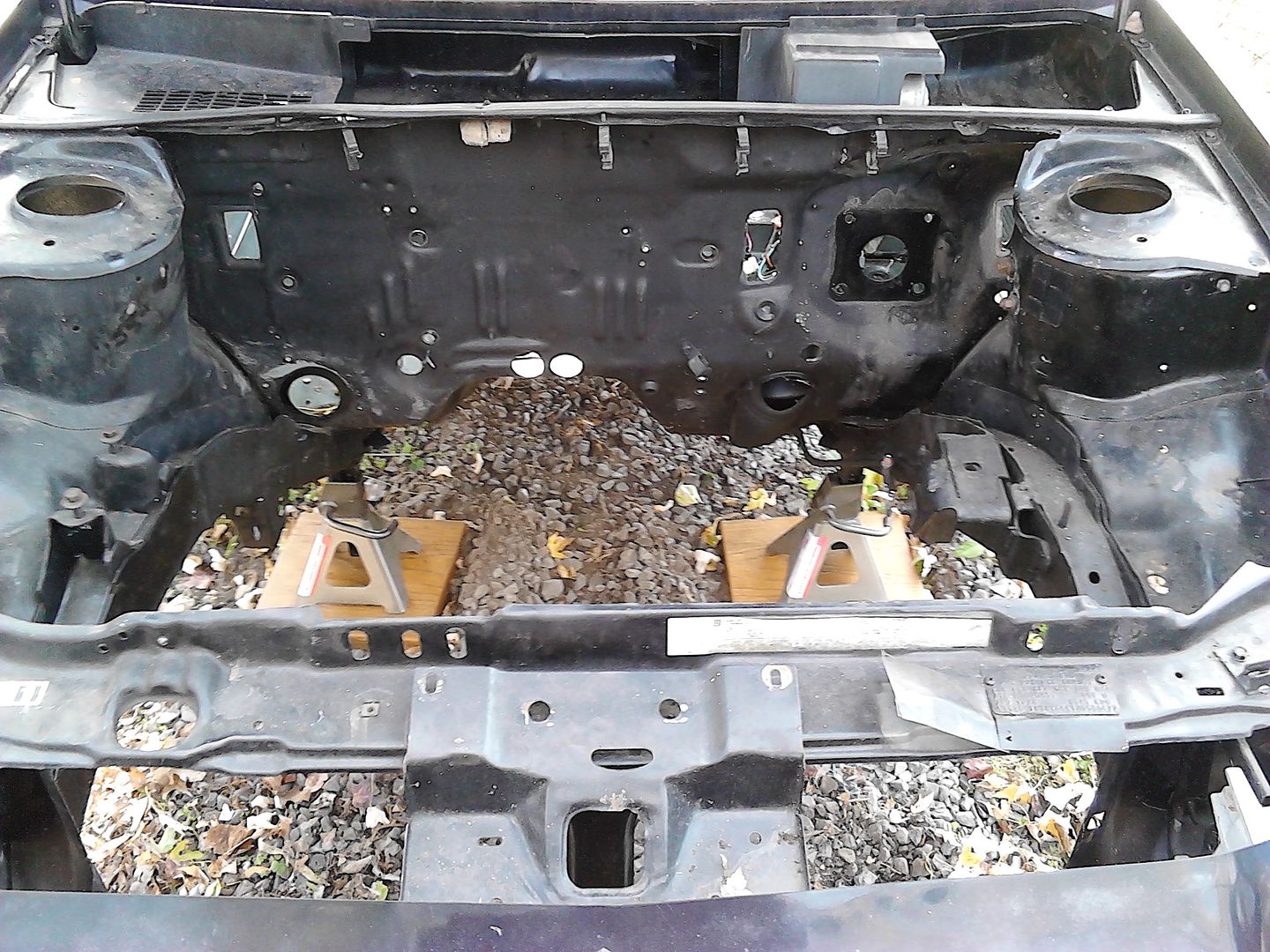
My intention is to install the harness in the engine compartment next(for mock-up); prior to shielding it with loom.
(At the moment, the engine bay is completely bare)
If any of you are 100% sure about the size hole for the BH grommet, that would help out.
I'm thinking it's 3", or very near there(3.25"), as I used a dial caliper on the grommet.
but a dial caliper on a rubber grommet is never a good idea.lol
And I know the wrong sized hole can really jack things up for me here.
So, if you know, let me in on it please.
Here's the engine bay as it is now:
Some simple cleaning, and ready to paint(after mock-up).
10-27-2014
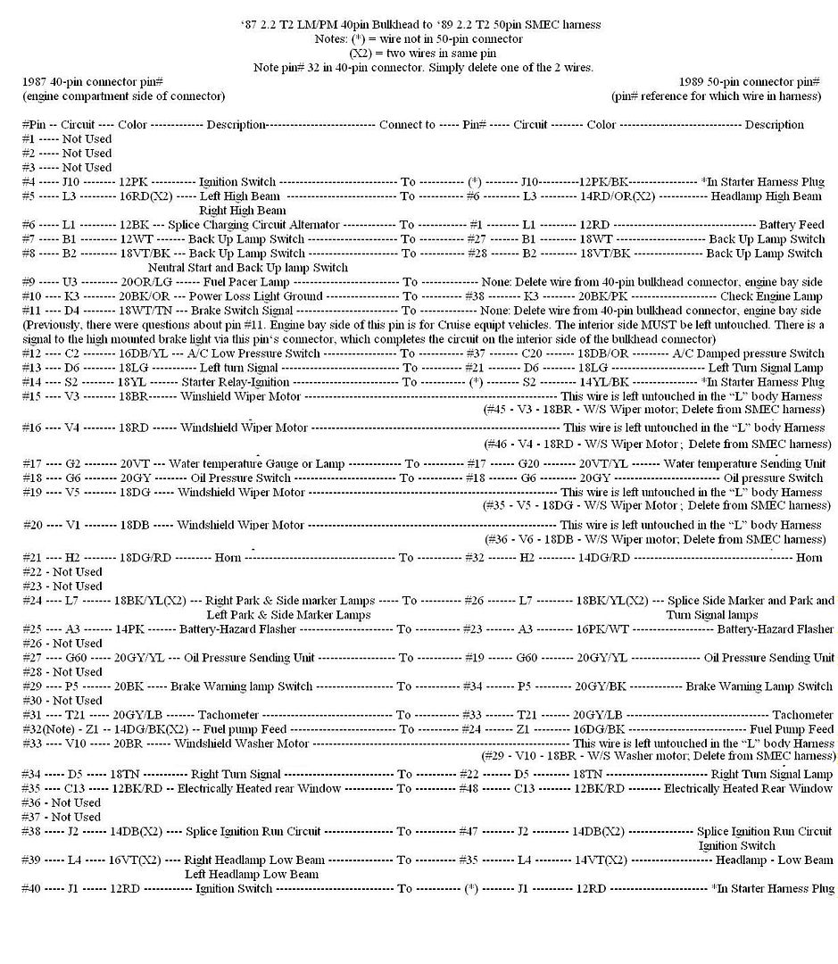
Here's the latest pin-out diagram for the conversion.
(A few changes, but nothing extremely difficult; figured out the "pin-#11" deal)
http://www.turbo-mopar.com/forums/sh...ess-conversion
 Posting Permissions

 Reply With Quote