The transplant is ready, time to prep the patient for surgery.
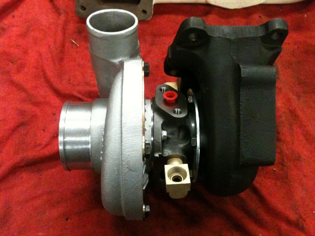


The transplant is ready, time to prep the patient for surgery.

I'm sure it's on your list, but I would go ahead and put some high temp anti-seize on the turbine housing bolts when you clock the turbo. It'll most likely save you a headache down the road.
Its already on there lol. We install a lot of O2 sensors and many come with a packet of high temp anti-seize. I save them all as one packet will easily do 10 sensors. So anything I think might need to come back apart in the future especially in the exhaust area gets some.
Prepping the patient.
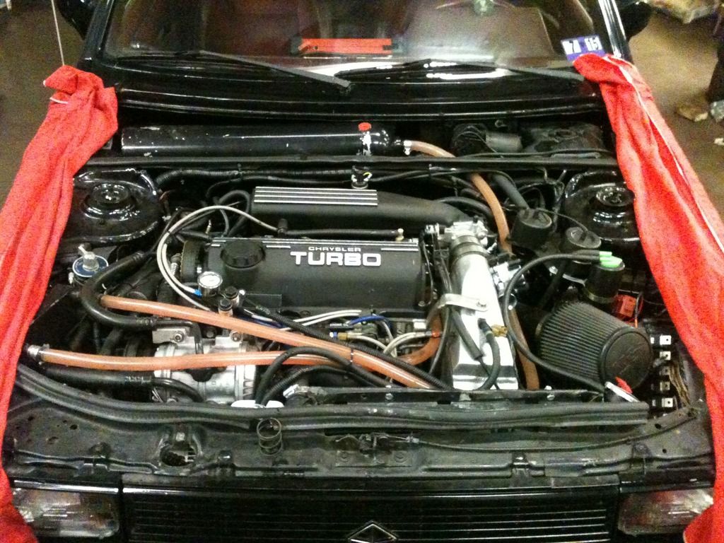
It's been a while but I'm back at it for now. Started by removing the exhaust. I made it a one piece unit for easy removal.
[IMG][/IMG]
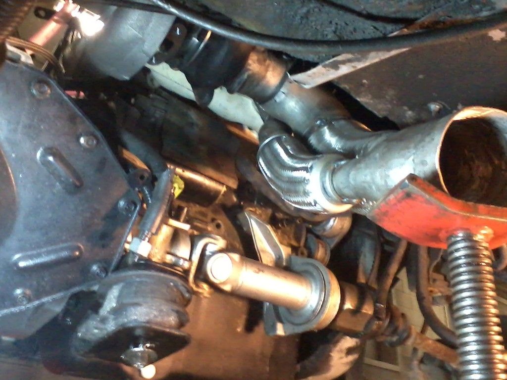
K-Frame will also need to be pulled to change the turbo from the bottom. We have an excellent alignment machine to realign the car after I get it all back together.
[IMG][/IMG]
With the frame out of the way there is plenty of room for the swap. Notice the 4th motor mount I added some time ago. Its holding up nicely. Cars with a manual trans and rod shifter would really benefit from this mod.
[IMG][/IMG]
Now we have a nice shot at the turbo with all that stuff out of the way.
[IMG][/IMG]
Looking good. I like your 4th motor mount. It's reminiscent of the Shelby ones that were offered for the cars.
I just read through all 14 pages of this thread and all I can say is "WOW!!!" This is one impressive feat of engineering! I wish I could give you a car and a blank check and just say "DO IT!!!!"
I have lots more ideas but time and money put a damper on most of them. I have always wanted to do a hybrid dual engine car on a budget. Looks like that might actually happen after I get this Omni back on the road.


I think it would have been fun to see what it would do on a smaller turbo. Now its just a matter of how fast do you want to go? Not sure about combining the two flowpaths when you are dumping them right after. That reminds me, how has the 4.7L TB been holding up? Any leaks?
Last edited by Ondonti; 04-27-2015 at 06:37 AM.
Brent GREAT DEPRESSION RACING 1992 Duster 3.0T The Junkyard - MS II, OEM 10:1 -[I] Old - 11.5@125 22psi $90 [U]Stock[/U] 3.0 Junk Motor - 1 bar MAP [/I] 1994 Spirit 3.0T - 11.5@120 20 psi - Daily :eyebrows: Holset He351 -FT600 - 393whp 457ft/lb @18psi 1994 Spirit 3.0T a670 - He341, stock fuel, BEGI. Wife's into kid's project. 1990 Lebaron Coupe 2.2 TI/II non IC, a413 1990 Spirit 3.0 E.S. 41TE -- 1993 Spirit 3.0 E.S. 41TE -- 1994 Duster 3.0 A543 1981 Starlet KP61 Potential driver -- 1981 Starlet KP61 Parts -- 1983 Starlet KP61 Drag 2005 Durango Hemi Limited -- 1998 Dodge 12v 47re. AFC mods, No plate, Mack plug, Boost elbow -- 2011 Dodge 6.7 G56
Throttle body has worked out fine. I have to clean it once every couple of months as carbon causes it to drag a little. Other than that its not been a problem.
The exhaust manifold has been really hot as seen is these pictures. My relocated battery cable took a beating. The shielding even burnt off.
I am going to install a much better heat shield this time around. Considering that manifold had to be red hot dozens of times the VHT 2200 degree flame proof paint held up really well.
Test fitting of the new exhaust manifold.
Bottom row of nuts had to be installed before the manifold was pulled up to the head. There is very little room to get the nuts started.
New turbocharger set in place to get the housings clocked right. This manifold moves it over nearly 4 inches to the drivers side. This will work out great for my setup as its nearly a straight shot into my intercooler now. Before I had to use a tight S pipe coming out of the turbo and going into the intercooler.
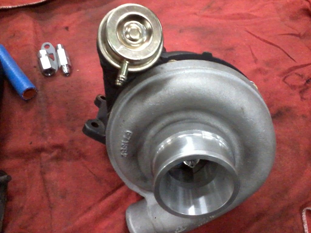
Somehow along the line I forgot that my wastegate can would not work with the new turbo. So I whipped up a last minute solution for the bracket. I cut a clutch steel from an automatic transmission in half and welded both pieces together with a small offset.
I used the original turbo compressor plate as a pattern so I could drill the bolt holes. The welding looks terrible but it will hold I'm sure.
Welded on an old shock washer to the top, drilled it to match the wastegate actuator and added an extra brace for insurance. Lots of grinding and a little 2200 degree paint and we are back in business.
Tried the newly fabricated downpipe to see how close my guess-timation was and it actually fits pretty well. The flex couplers have plenty of bend in them so I can push the end of it where it needs to be and still have more left for the motion of the engine under acceleration. This does not amount to much on my car with the extra motor mount.

Looks really good! Can't wait to see what it does.
Dont push the red button.You hear me?
I am a little worried about putting those flex pipes in tension to make the bend, that's how ive seen those fail before. is there anyway you can make the bend without bending the flex pipe?
Yeah bending it was not my first choice but I'm hoping that since it does not have to bend much when its running it might last me a couple of summers.
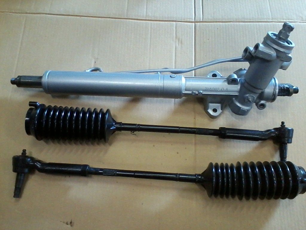
While I had the k-frame out I decided to rebuild the rack and pinion. After sitting all night when the temperature was cooler the steering would be really stiff for the first 2 or 3 minutes after starting the car. There were no leaks to the outside and it was a 2.5 turn lock to lock 14 to 1 quick ratio rack. I have been looking for one that I could afford for nearly 2 years with no success. Back in the mid 80's we used to rebuild these since Chrysler had very few choices for reman units and new ones were outrageous. Starting in the early 90's remans became more plentiful and much cheaper so we never fooled with rebuilding them anymore. Service manuals eventually left rebuilding most of them out too. Several companies today rebuild these units but you have to send them yours and it usually runs about 125 to 200 plus shipping to get them done. Even though its been over 25 years since I rebuilt one I thought that I would give it a try and see if I could still do it as the kit only costs 18 dollars for the Saginaw unit which is what the fast ratio ones in an L body and most others were.
First up is the rack itself.
Removing the bellows to get to the inner tie rod ends revealed one of the shock dampers or stop bumpers as some call them had split and popped over the inner joint. These can be left off as far as I know but when cutting to the stops you get a little more noise and it adds about a quarter turn to the overall steering (an eighth turn on each side). This would probably let the tire hit the transmission a little harder as most of them rubbed anyway from the factory. You would just need to be careful and not be holding it in a full lock turn and burn the inside edge off the tire I guess.
There is really not much to a rack and pinion. If you can rebuild an automatic transmission or an engine a rack would be child's play in comparison. Its surprising that there is very little information on the internet about how to do this yourself. I recommend that if you are to tackle this make sure you have access to a service manual for the rack you are rebuilding. Disassembling the rack without marking things like where the valve assembly is sitting when the rack is straight ahead will cause all kinds of problems when you try to put it back together. Read the instructions a few times BEFORE you start taking things apart. Here are the major parts when disassembled.
After being cleaned up.
The kit I used. Part number 8067.
First up is number 12, the valve assembly. It has one piece sealing rings like many transmissions do. Digging around in some old information I found a Chrysler bulletin that said if you have little or no assist or a stiff steering complaint when the car is first started up cold then these rings need replaced with the "green ones". As you can see mine had the original orange ones and the kit I bought fortunately had the green ones. I think this alone would have cured my problem.
I stretched the new rings on with a small pick. Just becareful not to nick or cut the new rings.
There are different ways to get the rings back into the proper size. One way I do it is to leavethe lube on them that I used to make them slip on easier then run several bands of electrical tape around them VERY tightly. This keeps pressure on the rings and compresses them back into shape. Usually takes 30 minutes or more. The tape peels back off without pulling on the rings since the lube keeps it from sticking.
Or you can do it like this and its faster. I take a plastic spray paint lid and cut the top out. Then cut all the way down one side. Now you can wrap that around your sealing rings and add a hose clamp or two and tighten them down tight. This compress the seals very quickly. Leave it for 5 minutes and when you remove it the seals will be the perfect size.
Same thing goes for the ring on the rack assembly.
Soon to be continued.........
With everything removed out of the housing, or tube assembly as its listed, it should be nice and smooth through the middle where the rack seal rides. Any major scratches in that area and you need to find another housing.
Of course the same is true in the bore where the valve assembly goes. The area where the 4 sealing rings goes has to be very smooth. Also notice there are several machined groves in this bore that the seals must go by to get the valve into place. This is why its important to have the rings compressed in flush or even below the surface of the groves they ride in. Once together they will expand back out within a short period of time and seal everything up. If you leave them sticking out they will get cut or deformed and you are going to have all kinds of steering assist problems.
Going back together its easiest to install the inner tube seal with the rack itself. Just wrap some type of heavy paper around the end of the rack that has the teeth on in and now you can slide the seal onto the rack without cutting it on the teeth. Drop the toothed end of the rack into the tube and slowly lower it till you feel the seal start into its shelf. Use a soft hammer and tap on the end of the rack till the seal is driven in about 3/8 of in inch. It will hit solid when its home. The seal goes in this direction.
The pinion bushing goes in the bottom of the valve bore. There is a groove that it sits in.
Right above the bushing is the lower valve seal. This seal, like several in the unit, have the lip made onto the face of the seal instead of inside its opening. This prevents you from driving it in with a normal seal installer. So I went through our freeze plug assortment and found some freeze plugs that would sit over the lip and still push on the rim of the seal. Worked perfectly.
Next up are parts 23, 24 and 25. These hold the seal for the passenger side of the tube and rack. They of course go in after you put therack in. A locking ring and snap ring go in last to hold everything in the passenger side. Considering you can have a couple thousand pounds pushing against these parts they need to be in right.
mini project rack rebuild soon to be concluded.
And now the conclusion
Once the rack is in and the seal, bulkhead and bushing are installed you should be down to putting in the snap ring.
At this point you can test your work. Remove the two steel oil lines if you have not already and apply as much air pressure as you can to each fitting. You should have no leaks if everything went together good. 200 psi will not hurt anything as this part of the rack sees 2000 psi in normal use. If its sealed up continue on.
Install the lower pinion bearing and its snap ring.
The factory service manual makes a big deal about installing the snap ring with the bigger lug counterclockwise from the smaller one. I guess this is to make sure you don't put it in upside down as snap rings have a sharp side and a rounded side. However the one that came with the kit had the same size lugs on both ends.
Center the rack the best you can in the housing tube. Now drop the pinion/valve assembly into the housing. Here is the tricky part. The pinion is helical cut so it turns as you drop it in just like a distributer does when you install it in a lot of engines. It took me a couple of tries to get it in so that it lined up with the marks I made BEFORE I tore the unit down. When its in properly you should have the same amount of turns side to side from the center. It should be about 1.25 turns left or right. This will prevent your steering wheel from being upside down or off to one side. Here are the marks I made with a file laying against the flat side of the splined pinion shaft BEFORE I took it apart. If you take it apart without doing this first you will have to guess or maybe use my picture to get It close on reassembly.
Install stub shaft bearing, seal, dust seal and retaining ring. While holding stub shaft in position, torque locknut to 26 ft. lbs
I locktited my bottom pinion nut with 271 red locktite just in case.
Install rack bearing, spring and adjuster plug. Turn adjuster plug clockwise until it bottoms, then back plug off 40 to 60 degrees(about an eighth of a turn). Install locknut and torque to 50 ft. lbs. while holding adjuster plug in position.
Here is something to think about. The pinion and rack and lower pinion bearing have no lubrication. They are sealed from the power steering fluid in the other parts of the rack. This could be a problem with 30 year old racks. Probably would not hurt to pull the drivers side boot off the rack and add some grease on the teeth and into the end of the rack to help prevent these parts from wearing out in the next 30 years lol.
Finally the most important part of the build. Clean up everything and give it a good coat of paint!

Does that adjuster plug affect the rack stiffness, or??
The adjuster plug holds the spring against the cupped out "rack bearing" as its called. The spring keeps the tension on the rack to pinion gear mesh. If you leave it loose the pinion teeth will wear or break off because they will push the rack away from itself when you turn the wheel. The pinion teeth are smaller so they usually take the damage. The steering will lock up or become disconnected from the wheels, both ending in catastrophic failures. If you put the adjuster plug too tight then it will pinch the rack bearing directly to the rack causing a very stiff steering wheel effort but will at the same time be destroying the pinion as that is what the rack will be forced against. Just the correct amount of spring pressure is required to hold the teeth in proper contact with each other, any more or any less WILL cause severe damage to the rack and pinion at the very least and probably indirectly to your car and possibly to your self when it wrecks you.
 Posting Permissions


 Reply With Quote


