It's a shame you can't complete this. I wish I could jump on it, but my own projects and life right now won't permit it. I've talked with Mike in person several times and his ideas and principles are solidly based on good engineering and physics.


It's a shame you can't complete this. I wish I could jump on it, but my own projects and life right now won't permit it. I've talked with Mike in person several times and his ideas and principles are solidly based on good engineering and physics.

I've done business with Mike and met him in person a few times. Certainly someone that can be trusted. I really hope someone buys the car, I really want to see it finished and perform!
95 spirit 3.0/543 15.0@91 N/A, 14.5@96 on a 50 shot RIP 87 shelby Z - project car, maybe I can drive it this year 91 spirit - roll it, chop the top, do some burnouts! RIP
Well, after dropping the block into the car, it did rain. So in an effort to keep things progressing I did some other stuff. Time to revisit a couple topics briefly mentioned earlier. Remember the ozone driver and coils? Remember the copper tubing that got a chrome look? Do you also remember the Arctic Air Charger? Let’s combine them all together and get another valuable step out of the way.
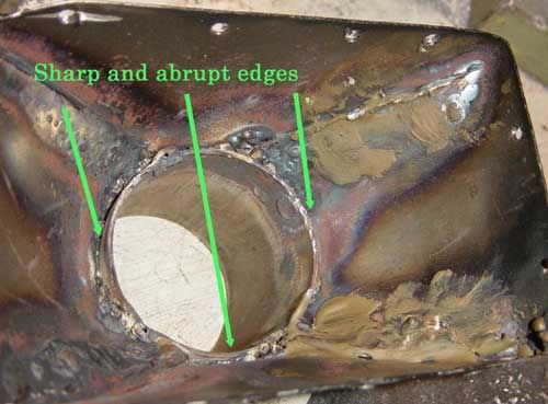
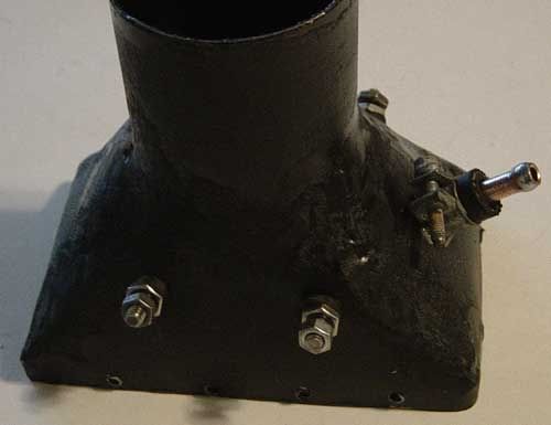
The piece that diverts air from the body of the AAC to the throttle body was hand fabricated. As such, there were unwanted abrupt edges where the round pipe met the formed sheet metal.
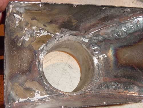
About 30 minutes with a die grinder got rid of the culprits.
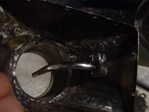
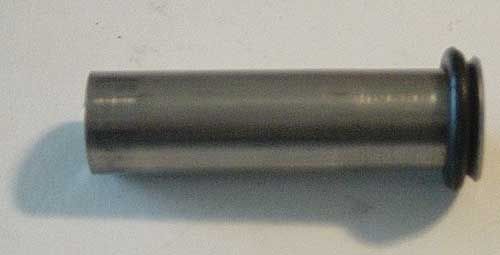
The copper tubing that got the chrome make-over is mounted in the throttle body side of the AAC. It is held in place with 2 pieces of ¼” fuel hose and clamps, backed with a smear of JB Weld. (You almost want to call me just to find out what that stupid tube does; and oh, by the way, weren’t there 2 of those suckers?!?)
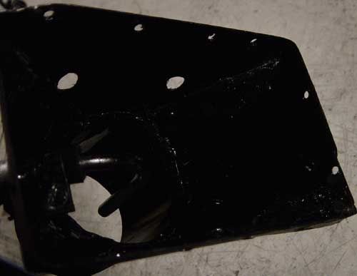
Why chrome it if you can barely see it, you ask? Because we are mounting the ozone coils in the same general vicinity. Ozone is extremely corrosive and will turn copper into a fragile stick of green crud in a couple of weeks (don’t want that getting sucked into the engine!). The chrome is durable in the presence of ozone. Furthermore, the steel inside of the housing itself would turn into a thin sheet of brown rust if not protected. So it gets a shot of enamel.
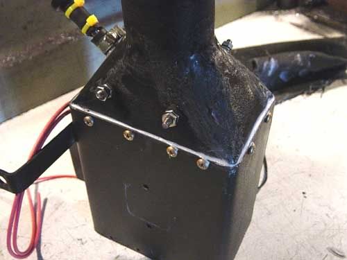
The holes in the sides will receive the ozone coils…
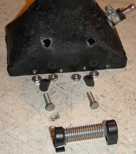
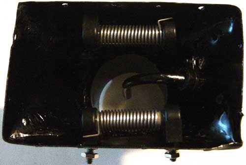
…which when mounted look like this.
At no point do the 2 leads touch the housing, inside or out. I used rubber hose to insulate the bolts from the housing and space things far enough away for safety. The bolts are stainless steel so they won’t rust. I’ll figure out where to mount the driver unit after the cylinder head is installed and I see what room I have. The leads should be as short as possible because the driver is putting out 7 kV at 25 to 37 kHz. When the wires are connected, the ends of the bolts will get rubber caps to protect them from emitting ions (diverting energy away from the ozone coils and possibly interfering with the ECU) and protect me from shock hazard.
More to come,
Mike
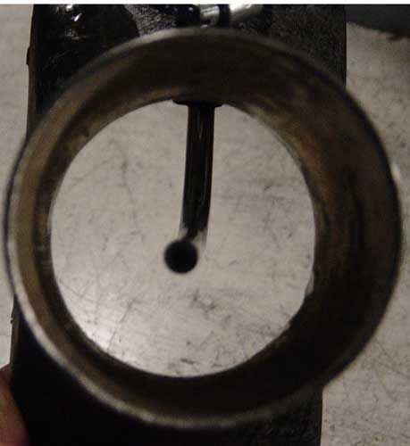
Looks like a pitot tube to me! Maybe to keep a constant pressure differential between the intake air and some sort of pressure/storage vessel?
The engine is in and together! I used a Mopar Performance 006 head gasket.
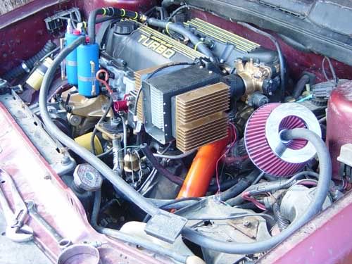
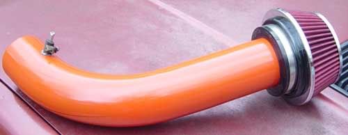
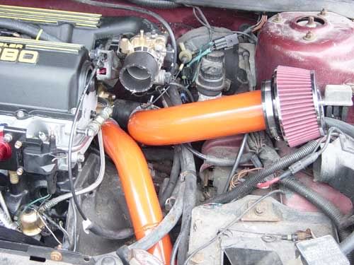
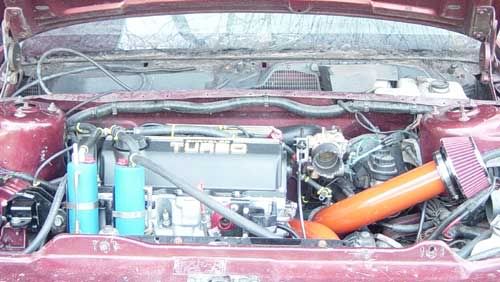
Now I can get things positioned and fitted. I want to carry the accent colors of the stripes along the bottom of the car to the under-hood area. I chose Street Hemi Orange for the intercooler pipes.
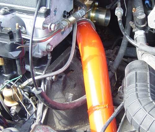
If you remember, there were 2 of those chromed copper tubes. The other one goes…
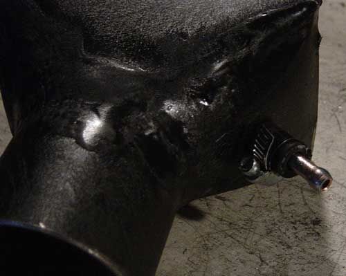
Which then goes…
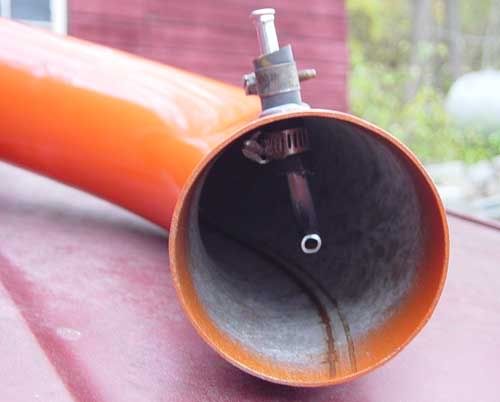
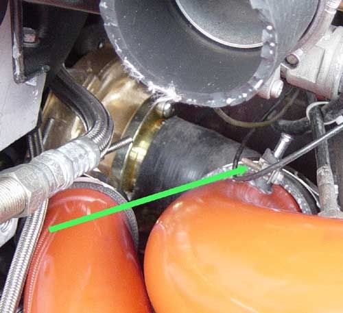
Notice the nipple on the top of the pipe right before the silicon elbow? Again, why chrome it if you can’t see it? I was already chroming one of them so I figured I may as well chrome them both.
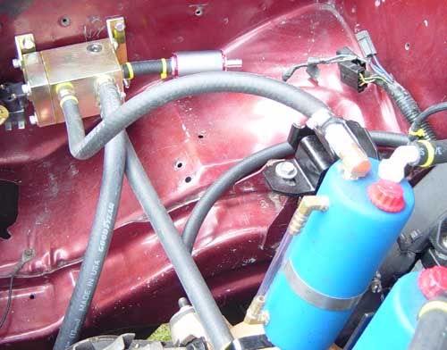
I may as well let the cat out of the bag. This is part of an Air Accelerator system to virtually eliminate boost lag. There will be an air tank mounted under the battery tray. It will be recharged with one of those 12 volt electric tire pumps, regulated to about 40-50 psi. Solenoids will divert the pressurized air to these 2 tubes. The principle works like this: if you take a 4’ rubber hose and cut a notch about 6” from the end, put the long end into a bucket of water and insert an air hose into the notch aimed at the short end; when you squeeze the trigger on the air nozzle, water will be sucked from the bucket and spray out the short end. The flow of air through the hose creates a vacuum on the back side, which pulls the water up and through. Similarly, with a high pressure velocity stream of air in a larger pipe, it will pull air from behind and create a rather massive flow of air in the direction of the pressurized air. Got it? It’s called an “air accelerator” (you can look it up).
The control panel has a switch labeled “Air”. This switch arms the electronic circuit that controls the solenoids. When the throttle is at least 80% and no boost is present, the solenoids open. As soon as about 3 psi boost is detected, the solenoids close, letting the turbo take over from there. When tank pressure drops by about 8 psi, the pressure switch will turn on the electric pump and recharge the tank. The pump is low amp, and takes awhile to fully charge the tank. When the switch is turned “Off”, the system is inoperative (daily driving versus race, for example). Some of the things I’m doing improve both performance and economy, some improve performance at the cost of economy, this one just improves performance without affecting fuel economy.
More to come,
Mike

Is that going to work on that side of the turbo? It's my impression that a stream of air hitting a fan (like the compressor wheel) tries to spin it backwards from it's designed direction of rotation. I can see it helping at the TB though.

Love it! The shade tree mechanic's flow amplifier!
Mike
"The Constitution is not an instrument for the government to restrain the people, it is an instrument for the people to restrain the government - lest it come to dominate our lives and interests." - Patrick Henry
Bad laws are the worst sort of tyranny.
- Edmund Burke
I think it might be sensitive to position, too near the turbo might not help much, but the turbo is trying to get a long sausage of air moving my sucking at one end of it, so some help at more of a distance from the turbo may help, since it will be making a relative vacuum just ahead of it. Myself, thinking along those lines I'd put it in the air filter housing... possibly use one of those "donut" type sprinklers around the pipe. Or do a reverse flow Coanda effect thruster type design in an airbox that takes a ring type filter. (Use a half donut type candle holder base with jet in center in the middle of a large vase or planter that approximates a parabola)Originally Posted by Force Fed Mopar

Though if you wanna really over-engineer the whole thing, it's possibly a pumping loss defeater (i.e. mpg gainer) by recapturing braking energy by compressing exhaust gas in an extra AC compressor on the drive belt, and using it as a sort of air "accelerator pump" for moving off again. Would work on N/A.
DD1: '02 T&C Ltd, 3.8 AWD. DD2: '15 Versa Note SV, replacing.. DDx: '14 Versa Note SV << freshly killded :( ....... Projects: '88 Voyager 3.0, Auto with shift kit, timing advance, walker sound FX muffler on 15" pumpers wrapped in 215/65/R15 H rated Nexens.... and a '95 phord escort wagon PnP head << Both may need to go :( ..... I like 3.0s ... so??? ... stop looking at me like I've got two heads!
Hmm, yeah could be...
I guess we'll just have to see. I wanted to keep it relatively simple.
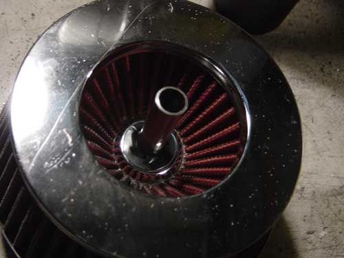
We’ve touched on the PCV system more than once so far. I mentioned the Inter Charger and Stratifyer, now let’s put sub-assemblies together and create a system. We have our 2 catch cans. One gets a PCV valve and the other a plastic check valve. The PCV side feeds the Stratifyer, then the Inter Charger. The other side is fed to the air cleaner. Starting with the air cleaner side, the center of the air cleaner is drilled with a ½” hole. A piece of ½” stainless tubing is flared on one end. A rubber O-ring with a ½” ID is placed over the tube. It slides up and out of the air cleaner from the inside, and a push clip holds it in place.
Hose is used to connect the elbow on the catch can to the nipple on the air cleaner, and looks something like this. The hose will be pull-tied securely.
I had to reconfigure the PCV valve as there wasn’t sufficient hood clearance the way I mocked it up.
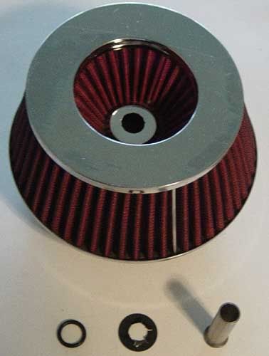
From the PCV valve, a hose connects to the inlet port on the Stratifyer. The outlet port is fed into the Inter Charger. This picture shows the stock Inter Charger as I am not allowed to disclose the modifications I am making. When installed, the Inter Charger gets a wrap to hold in heat and to hide my trick. From the Inter Charger a hose connects to the intake (pics coming later). Notice the heater hoses.
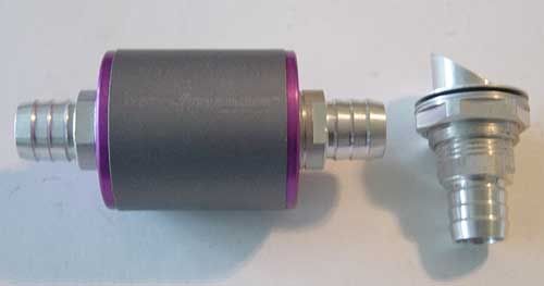
I want to turn you racers on to an idea whose time has come. There are larger Inter Chargers than the red one used on the Daytona. The “Purple” version is sold for diesel pick-ups and comes with a venturi tube.
This one accepts a ½” hose and has substantially more catalyst materials than the red unit. So here is what you do. Run a hose from your valve cover PCV port to a catch can as I have done. (I have quite a few of the powder coated wrinkle blue catch can canisters mostly un-modified and will sell them for $15 + shipping if anybody wants one or two.) Early log style bent valve cover PCV nipples might work better than the later straight versions. Run a hose from the catch can to the Purple Inter Charger. Mount the Inter Charger someplace where it can pick up some engine heat (it works better when it’s hotter). From there, mount the venturi as close to the turbo inlet as possible and connect the last 2 dots with hose. You can go to www.ExtremeEnergySolutions.net and see how it’s installed on the diesels to get ideas.
What happens is instead of the PCV gasses causing detonation, they will be conditioned and actually HELP combustion; make MORE power. You won’t have oil drops on the garage floor from a simple vent tube, you won’t have the issues with venting it into the exhaust, and you’ll go faster!
More a-comin’,
Mike
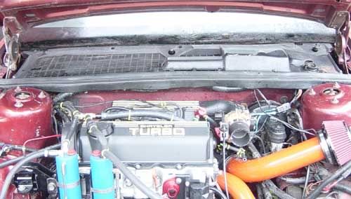
As with many projects there comes a time when lots of hours are spent, but not much progress can be tracked (especially with eye-catching pictures). I spent today running hoses and repairing wires. Since I swapped over to the E-coil, I had to pull the stock coil wires out of the harness and run them to the new location. The last time I converted to the newer coil I just added more wire to the existing wire from the stock location. I wanted this car to reflect quality, and the other way just doesn’t cut it. I used the split convolute tubing and cloth electrical tape so it looks stock.
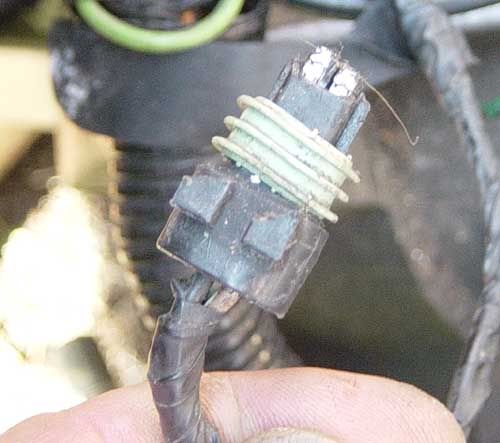
The coolant temp sensor connector was trashed. The lock tab was broken off, and the terminal part somehow got mangled. It got replaced as well (see picture above and below). BTW, I’m soldering all connections and using heat-shrink tubing (which you can’t see because it’s covered with the split convolute tubing and tape).
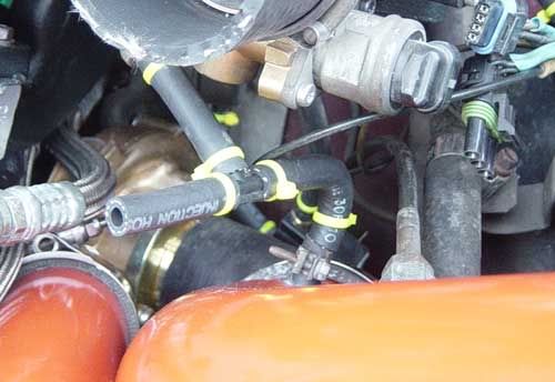
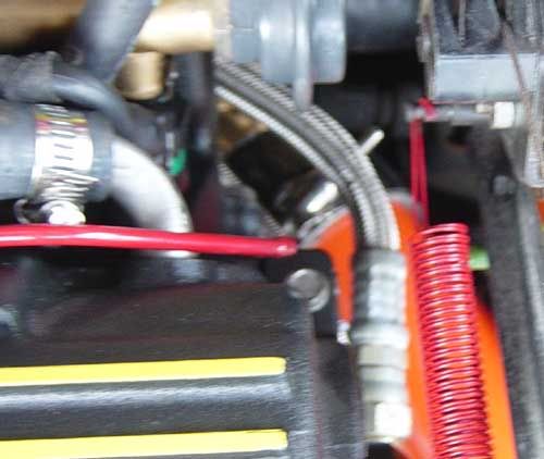
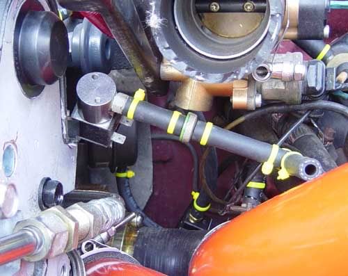
I had to do a repair to the air temp sensor connector as well. The connector had been replaced previously, but it was just twisted to the old wires; no butt connectors, solder, or even tape. The old wire was cracked in several places. Consider it fixed. For the hoses, I’ve been favoring yellow pull ties. They do a reasonable job of securing vacuum/boost hoses (especially at low boost levels) and accent the fins in the valve cover and intake. The following picture illustrates how I tie both the chromed copper tubes together, and tie the tank vent function into the rest of the intake tract.
More to come,
Mike
That car blew my 60.1 mpg 3 banger Geo clean out of the water! I found that every 100 lbs off the Geo let it gain 1 mpg. I got 140 lbs out of it and never went to Lexan or cutting of any metal. I did NOT give it the Matchbox treatment! I would have used 0 wt oil if I was competing in a mpg contest. This car ran 19.9s at 65 mph.
My 95 Plymouth Neon gets a best of 46 when driven at a steady 55-60 mph on longer trips. It is a four door that has had the power steering removed, cheap V8 camaro twin tip muffler at the rear, automatic equiped TB on my 5 speed motor, no cat, lighter rims with smaller size rear tires to cut down rotating wt, and a home made CAI. It still has A/C but when I use it on a long trip it uses an extra 4 mpg! This car runs hgih 15s at 86 mph.
My 05 SRT4 was getting a FANTASTIC 36 mpg at a steady 55-60 mph on longer trips when it was a no toys stage 2 set up, BFMIC, and a E1 enforcer turbo from FM. It now gets a best 33 with the same driving conditions since I put on a S3 turbo. This car now runs 12.17 at 115 best et.
The wifes 01 Voyager went from 24 to 26 mpg by replacing the air filter with three layers of screen wire.
Old Matchbox was getting a miserable 23 mpg with the tall block 2.5 (417P & 423S jets) but should get better now with the fresher common block 2.5 that was dejetted a bit to 404 jets on both sides of the carb.
[SIZE=3][COLOR=#000000]47 Time NHRA/IHRA drag race champ-----84 Plymouth Horizon/1 of 84 HO equipped from the factory/1910 lbs, 2.5 with carb, nearly 315,000 miles-----04 SRT4/S2 with S3 turbo/12.17 @ 119/DOTs/93 Octane/SOLD-----2003 PT Cruiser GT, won a True Street class at the 2017 National Muscle Car Association World Street Finals-----2010 Toyota Prius/my delivery truck, 77.9 mpg best and NOT A PLUG IN, nearly 230,000 miles and way over 5600 miles per month! [/COLOR][/SIZE]
Taylor, I am extatic that you are playing and researching. For the record, you're getting much better results than most, and that says alot! Keep up the research and experimenting. It only gets better.
Mike
I'm getting 30 mpg in normal country driving in my full-weight Daytona right now. Stock 2.2 T2 long block w/ a FM 475 cam, 2-piece intake, 52mm TB, ported exhaust manifold, stock T2 Garrett w/ ported hot side, 3" exhaust, junkyard Izuzu NPR intercooler, +40 injectors and a self-tuned 3-bar cal. Running Kendall GT-1 20w50 oil in the engine (due to a low oil pressure condition caused by no restrictor in the block, I think) and 5w20 oil in the A520 trans (3.50 gear). Currently running 205/55/16 in the front and 205/60/16 in the rear. On a long interstate hwy trip I get 35-37 mpg while running 70-85 mph. This is on 93 octane. Car has run a best of 9.56@78mph in the 8th.
The air filter mod is similar to what I'd have guys do with their "dry" nitrous nozzle. We'd remove the deflector tip to shoot straight down the velocity stack built into their filters... just the high speed gas helped amplify the natural air flow, that is it added air flow over what would be ingested without it.
Mike
"The Constitution is not an instrument for the government to restrain the people, it is an instrument for the people to restrain the government - lest it come to dominate our lives and interests." - Patrick Henry
Bad laws are the worst sort of tyranny.
- Edmund Burke
Lol triple post...
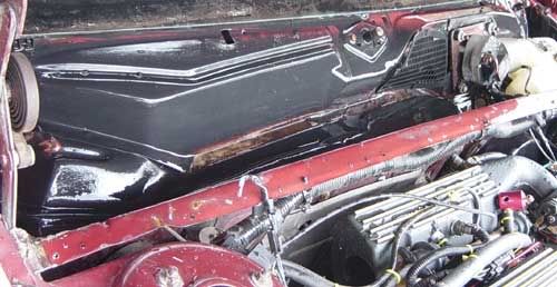
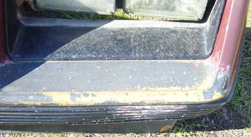
Another entry that qualifies as lots of time for not a lot of pics. I removed the cowl cover, scrubbed it up, and cleaned underneath.
The cowl cover was then reinstalled looking fabulous.
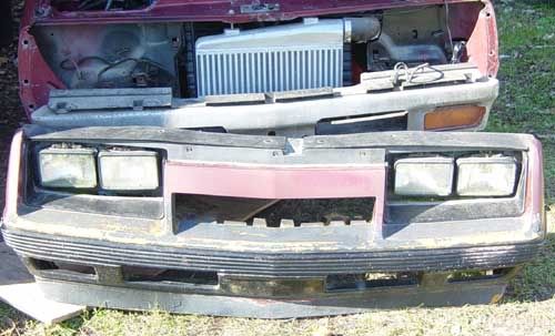
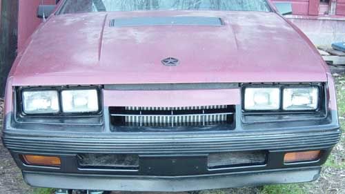
The front fascia had that “fresh woke up in the morning” look with scuffs and scars. (Notice the FMIC?)
After a little make-up it looks much better.
I removed the grill insert and painted it semi-gloss black. The head light bezels got shot the same semi-gloss black as the grill. The rest of the fascia got sanded and painted with a satin finish trim paint. If nothing else, the yellow scuff marks disappear into the black trim paint. A marked improvement. The front fascia was reinstalled with new nuts and washers, as the originals were not there when I got the car (the fascia was just hanging there). I was tempted to paint the grill and head light retaining rings gold, but I resisted.
As always, more to come (for awhile, anyways; spending money I don't have trying to keep it progressing so somebody buys it).
Mike
Sorry for that! That is courtesy of my rooted color nook! I don't know if it's the site/android combo or what, but hopefully THIS post isn't three times the fun!
I'll try to fix it once I get to a real computer ...
Mike
"The Constitution is not an instrument for the government to restrain the people, it is an instrument for the people to restrain the government - lest it come to dominate our lives and interests." - Patrick Henry
Bad laws are the worst sort of tyranny.
- Edmund Burke
Consider this Saturday's post. To quote Harry Potter's uncle, "There's no post on Sunday".
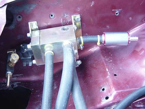
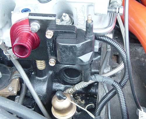
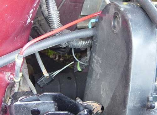
The charcoal canister was missing from the car when I got it. I decided to do my own version of an EVAP system. From the vent tube I ran a steel line across the engine to the driver’s side. It got painted red.
A solenoid mounts between this red steel tube and a check valve, then gets tee’d into the Air Accelerator hose at the turbo inlet. The check valve prevents the pressurized AC air from putting pressure in the fuel tank, and has a built in orifice that restricts flow.
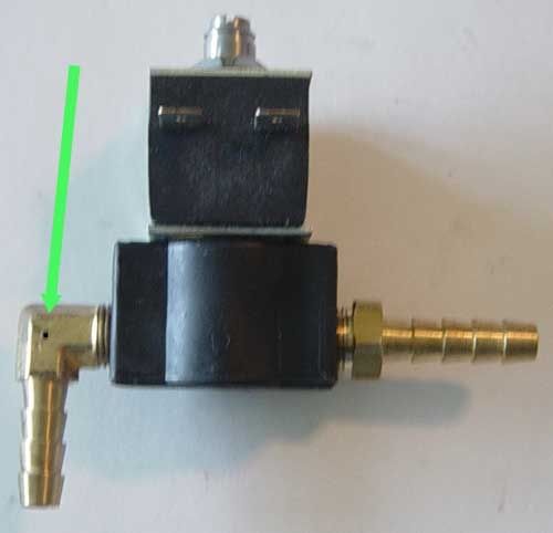
The solenoid I’m using looks sort of like this.
This particular solenoid will be serving duties as my wastegate solenoid. Notice the small air bleed. The factory solenoids don’t flow enough to deliver smooth operation with the Wastegatre Boost Controller (Wastegatre.com). This one flows about 3X air as the factory job. I have several of these solenoids and am using them for the Air Accelerator as well. On a side note, the Air Accelerator has another benefit in that it helps to cool the air. The tank will be at ambient temperature, but at high pressure. When the pressure drops (volume increases at the discharge nozzle) it creates a cooling effect. You know how your air compressor tank gets hot after running for awhile? Well, this is the opposite effect.
More later,
Mike
My apologies for not posting earlier. We had a very wet snow that took down bunches of trees and power lines. We didnt have power for about a day, and internet was out for much longer. It got worse after I took this picture of my front yard. I checked all the usual internet places; library, McDonalds, etc. There was no internet for at least 2 towns! Alas, since you are reading this, indubitably I have found internet access.
Posts might be sparse for a couple weeks. I have been invited to speak at the HHO Games (hhogames.com) in Sarasota, FL on November 11-13. I was given rather short notice and have lots of preparation work to attend to. Please forgive me, but check back often.
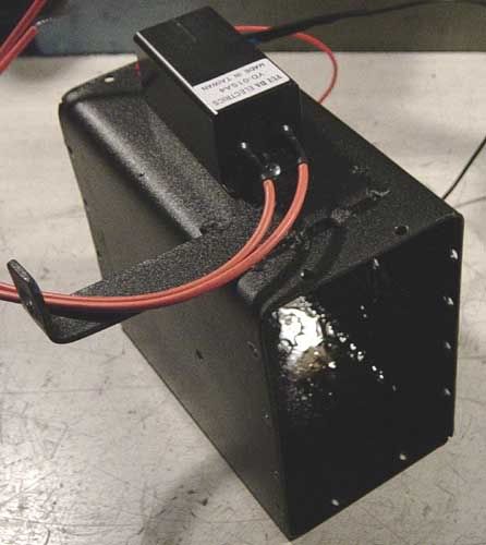
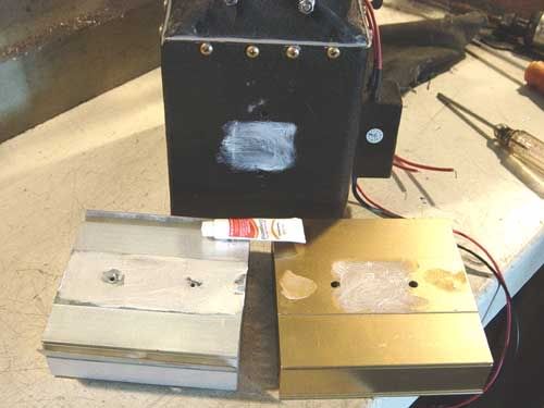
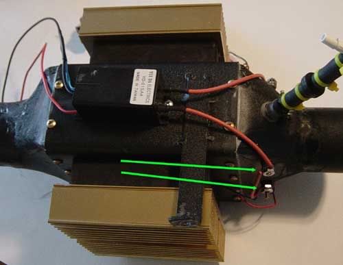
Revisiting the Arctic Air Charger assembly one more time, I actually put it together and took it apart several times as I added more stuff. For this last time I spray painted the inside to help prevent rust. The small electronic box on top (bottom when its installed) is the driver circuit for the ozone coils.
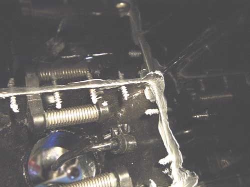
Quite awhile ago someone asked me just how I intended to seal this thing so it wasnt spewing precious boost out all the seams. My answer is, probably the way the factory would have done it back in 1985 if they were building such a device Silicone sealant!
An inside look.
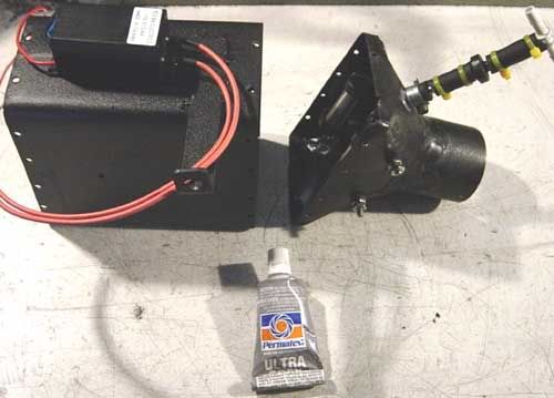
I started with the loaded end. After the first end cap was installed and sealed, I reinstalled the Peltier chips. The chips need to have thermal conductivity with that which they are to heat and cool. I used Heat Sink Compound to help dissipate the heat and cold.
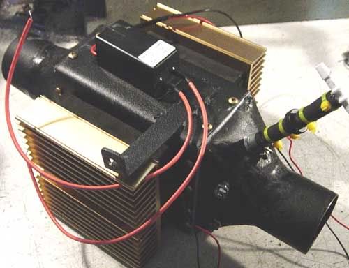
It then goes back together the way I had it before.
The last step is to connect the wires from the driver circuit to the coil connections (green arrows).
More to come.
Mike
Last edited by mpgmike; 11-02-2011 at 10:28 AM. Reason: spelling
 Posting Permissions

 Reply With Quote