Page 3 of 5 FirstFirst 12345 LastLast
Results 41 to 60 of 91

Thread: T-III Reliability improvement

  1. #41
    turbo addict
    Join Date
    Sep 2008
    Location
    Salt Lake City UT
    Posts
    1,603

    Re: T-III Reliability improvement

    will a belt tension gauge like this work?

    I hope so cause i bought one for $26 shipped, if not i guess i could re-sell it

  2. #42
    turbo addict
    Join Date
    Dec 2005
    Location
    Bristol, CT
    Posts
    2,722

    Re: T-III Reliability improvement

    It looks like basically the same thing but with an offset. Before you take the car apart I would test it out on the current belt and see what you get for a reading.

  3. #43
    boostaholic
    Join Date
    Oct 2006
    Location
    Southern Wisconsin
    Posts
    1,043

    Re: T-III Reliability improvement

    I dont think that one works very well.....

  4. #44
    turbo addict
    Join Date
    Sep 2008
    Location
    Salt Lake City UT
    Posts
    1,603

    Re: T-III Reliability improvement

    Quote Originally Posted by Lotashelbys View Post
    I dont think that one works very well.....
    Why? Not that i don't believe you i am just wondering

  5. #45
    turbo addict Turbo Mopar Contributor iTurbo's Avatar
    Join Date
    Dec 2005
    Location
    Gillette, Wyoming
    Posts
    5,384

    Re: T-III Reliability improvement

    That's the tension gauge I use. It works although I haven't ever tried another kind.

  6. #46
    boostaholic
    Join Date
    Oct 2006
    Location
    Southern Wisconsin
    Posts
    1,043

    Re: T-III Reliability improvement

    I dont think it fits between the cam gears very well and the gauge will be back almost to the firewall if you can even get it in place. Just try to find the correct one and be done with it....

  7. #47
    turbo addict Turbo Mopar Contributor iTurbo's Avatar
    Join Date
    Dec 2005
    Location
    Gillette, Wyoming
    Posts
    5,384

    Re: T-III Reliability improvement

    While the offset is a little funky it still fits just fine. I have mine on the other way so the dial sticks out above the A/C compressor so the dial face is facing the driver side which is a little awkward. It's actually very easy to use, but you gotta make sure the claw is clasping the entire width of the belt. I do like the other gauge that everybody else uses and would like to get one to replace mine someday.

  8. #48
    Hybrid booster
    Join Date
    Dec 2008
    Location
    United States
    Posts
    857

    Re: T-III Reliability improvement

    The well publicized high spring rate on the T-III is a popular topic when discussing belt failure. What is worth mentioning is that because of the smaller spring coil diameter, the wire diameter, and the amount of coils; the differential spring load, on the T-III, is higher than the 8V spring. This is the significant offender to belt durability. The rotating turning torque rises and falls with such amplitude that it generates belt tooth shearing force, on pulleys that have insufficient belt wrap. Specifically, the excessive rotational loading and unloading is met across only 9 teeth of the intake pulley. The raised retainers lower the closed and open spring rates but more significantly reduce the differential loading. These directionally correct retainers, at a .075"-.085" higher installed height, can reduce the differential load by approx. 15-20%, depending on the actual spring rate. Although, this still produces closed seat pressures that exceed the stock 8V roller spring. Machining an additional groove in the valve-stem allows for the original retainer to be raised .100" and places the installed spring load closer to the 8-valve stock spec. This increase in installed height has further impact on the differential (open vs. closed) spring pressure. This reduces the rotating oscillation torque by an additional 5-10%, which was not addressed in a retainer vs. stem-groove discussion months ago.

    To potentially accomplish the ideal position would require machining the additional groove in the valve stem and the use of a .010”-.025" modified offset retainer. Please note that the total amount required for a specific application is based on the actual measured load of the spring being used and the desired RPM range. Doing this can yield nearly a 25-35% drop in rotating oscillation torque depending on the total offset amount chosen. At this point, the resulting closed valve seat pressures are nearly at stock 8V roller specification, which was capable of 6500-6800 RPM. This may now be applied to a T-III valve that has less head area and opens nearly .100” less.

    Another contributing factor that doesn’t seem to surface is the modification of cam timing, on the T-III. The position of the cams relative to each other and their relative position to the crank are sometimes altered to increase performance. The belt tensioning tool is required to properly maintain a critical tension set-point and a specific belt operating frequency, for reasons mentioned above. When the cams are aggressively adjusted, relative to each other and the crank, the “normal” belt operating frequency is disturbed which can require a tension change to compensate for the resulting change in belt frequency. This can sometimes be visually observed or tested by maintaining the specified belt tension and modifying the cam angles, primarily the intake cam. As the engine is transitioned through an RPM operating range, the notable belt resonant RPM will change as a function of cam angles, tension, and the belt being used.

    The intermediate pulley reduction size and resulting speed increase of the oil pump, on the T-III, was due to anticipated valve train oil demands. This over-taxing change later required the introduction of “matched” Melonized set which generated an “equal” surface finish for the intermediate shaft and oil pump gears. The anticipated oil demand increase was required to over-come the compounding losses realized at the balance shaft assembly, while still being able to deliver adequate oil to an increase in valve train hardware. This was all expected from a pump that was designed without ever considering these added demands. If consideration is being made to reduce the intermediate shaft speeds, to standard 8V levels; it would strongly be advised to remove the balance shaft assembly and block the oil delivery hole, as many do. On high RPM applications, it should be noted that the balance shaft assembly maintains a 14,500 RPM durability limitation, due to bearing failure. This equates to an engine speed limit of 7250rpm caused by balance shaft sprocket gearing.

    If the decision has been made to reduce the oil pump speed - there are adjustable sprockets for both 8V and 16V applications. The thought may be to use the inner adjustable hub for 8V with an adjustable 16V sprocket and modify accordingly for offset purposes. This will support the proper hub diameter, pulley width, profile, and pitch required to slow the oil pump to standard speed. While an 8V pulley can be utilized, the production Mopar belt consumes 100% of the usable surface, permits zero tolerance for of center positioning, and does not mesh with full accuracy to the 16V belt. Combining the adjustable components for the reasons listed above can make for an accurate replacement pulley that meets stock specification requirements.

    Note that valuable belt length is being consumed. To counter-act this without the need for tensioner relocation, compare a production idler pulley to a tensioner-pulley and a significant commonality becomes apparent. The outer bearing race hub OD, on the idler, is incredibly close to the inner bearing race hub of the tensioner-pulley. With careful machining the outer tensioner-pulley OD can be eliminated and an adjustable idler is the result. This modified tensioner can be used in the standard location for an increase in usable belt length and also provides an additional belt/cam angle adjustment point, when installed on the front side of the engine. Adding an idler with minimal reverse flex loading while providing some increase in cam pulley belt wrap is a considerable improvement; while thorough rotational torque load reduction, balance shaft removal, and oil pump speed reduction can secure proven gains in durability.

    I hope this helps.
    Thanks

  9. #49
    turbo addict Pat's Avatar
    Join Date
    Dec 2005
    Location
    Rockville, MD
    Posts
    3,801

    Re: T-III Reliability improvement

    Quote Originally Posted by 5DIGITS View Post
    The well publicized high spring rate on the T-III is a popular topic when discussing belt failure. What is worth mentioning is that because of the smaller spring coil diameter, the wire diameter, and the amount of coils; the differential spring load, on the T-III, is higher than the 8V spring. This is the significant offender to belt durability. The rotating turning torque rises and falls with such amplitude that it generates belt tooth shearing force, on pulleys that have insufficient belt wrap. Specifically, the excessive rotational loading and unloading is met across only 9 teeth of the intake pulley. The raised retainers lower the closed and open spring rates but more significantly reduce the differential loading. These directionally correct retainers, at a .075"-.085" higher installed height, can reduce the differential load by approx. 15-20%, depending on the actual spring rate. Although, this still produces closed seat pressures that exceed the stock 8V roller spring. Machining an additional groove in the valve-stem allows for the original retainer to be raised .100" and places the installed spring load closer to the 8-valve stock spec. This increase in installed height has further impact on the differential (open vs. closed) spring pressure. This reduces the rotating oscillation torque by an additional 5-10%, which was not addressed in a retainer vs. stem-groove discussion months ago.

    To potentially accomplish the ideal position would require machining the additional groove in the valve stem and the use of a .010”-.025" modified offset retainer. Please note that the total amount required for a specific application is based on the actual measured load of the spring being used and the desired RPM range. Doing this can yield nearly a 25-35% drop in rotating oscillation torque depending on the total offset amount chosen. At this point, the resulting closed valve seat pressures are nearly at stock 8V roller specification, which was capable of 6500-6800 RPM. This may now be applied to a T-III valve that has less head area and opens nearly .100” less.

    Another contributing factor that doesn’t seem to surface is the modification of cam timing, on the T-III. The position of the cams relative to each other and their relative position to the crank are sometimes altered to increase performance. The belt tensioning tool is required to properly maintain a critical tension set-point and a specific belt operating frequency, for reasons mentioned above. When the cams are aggressively adjusted, relative to each other and the crank, the “normal” belt operating frequency is disturbed which can require a tension change to compensate for the resulting change in belt frequency. This can sometimes be visually observed or tested by maintaining the specified belt tension and modifying the cam angles, primarily the intake cam. As the engine is transitioned through an RPM operating range, the notable belt resonant RPM will change as a function of cam angles, tension, and the belt being used.

    The intermediate pulley reduction size and resulting speed increase of the oil pump, on the T-III, was due to anticipated valve train oil demands. This over-taxing change later required the introduction of “matched” Melonized set which generated an “equal” surface finish for the intermediate shaft and oil pump gears. The anticipated oil demand increase was required to over-come the compounding losses realized at the balance shaft assembly, while still being able to deliver adequate oil to an increase in valve train hardware. This was all expected from a pump that was designed without ever considering these added demands. If consideration is being made to reduce the intermediate shaft speeds, to standard 8V levels; it would strongly be advised to remove the balance shaft assembly and block the oil delivery hole, as many do. On high RPM applications, it should be noted that the balance shaft assembly maintains a 14,500 RPM durability limitation, due to bearing failure. This equates to an engine speed limit of 7250rpm caused by balance shaft sprocket gearing.

    If the decision has been made to reduce the oil pump speed - there are adjustable sprockets for both 8V and 16V applications. The thought may be to use the inner adjustable hub for 8V with an adjustable 16V sprocket and modify accordingly for offset purposes. This will support the proper hub diameter, pulley width, profile, and pitch required to slow the oil pump to standard speed. While an 8V pulley can be utilized, the production Mopar belt consumes 100% of the usable surface, permits zero tolerance for of center positioning, and does not mesh with full accuracy to the 16V belt. Combining the adjustable components for the reasons listed above can make for an accurate replacement pulley that meets stock specification requirements.

    Note that valuable belt length is being consumed. To counter-act this without the need for tensioner relocation, compare a production idler pulley to a tensioner-pulley and a significant commonality becomes apparent. The outer bearing race hub OD, on the idler, is incredibly close to the inner bearing race hub of the tensioner-pulley. With careful machining the outer tensioner-pulley OD can be eliminated and an adjustable idler is the result. This modified tensioner can be used in the standard location for an increase in usable belt length and also provides an additional belt/cam angle adjustment point, when installed on the front side of the engine. Adding an idler with minimal reverse flex loading while providing some increase in cam pulley belt wrap is a considerable improvement; while thorough rotational torque load reduction, balance shaft removal, and oil pump speed reduction can secure proven gains in durability.

    I hope this helps.
    Thanks
    Great info.

    Question thought..if one were to machine the extra groove in the valve to raise the installed spring height .100", instead of using an offset retainer to bring that height down to .075-.085, coulnd't a shim be used under a stock dimensioned retainer? Might be a simpler solution, plus, you'd have the ability to fine tune spring tension by use of smaller or larger shims if need be.

  10. #50
    Supporting Member Turbo Mopar Contributor 2.216VTurbo's Avatar
    Join Date
    Dec 2005
    Location
    SoCal the OC
    Posts
    6,675

    Re: T-III Reliability improvement

    Meh, what do you know Ken

    I had to read that post twice man, some serious pearls hidden amongst the words I had to sound out (BTW Melonized? A surface finish of some sort but?)I've never read anywhere about the balance shaft max RPM, thanks for that, I had kinda figured they weren't really 'hurting me' so I had left them until now but I'll be dropping the pan soon as 7250 is a joke with a well set up TIII.

    The way I remember it when I bought the Ti raised height retainers years ago (RDI Performance ones) that they were advertised as .100 raised, have you ever had your hands on a set from him? Got me wondering now if I need to do something more.

    I like Jackson's idea for an additional idler and reducing the OD of the other idler is another great tip You should hang around here more

    BTW, there was another smart guy around a while back, 4DIGITS+1, is he like a cousin of yours or something

    AJ (no More Alan) 84 Rampage RT TIII/568 Quaife 87 GLHS dealer optioned Red 16V Masi/568/Quaife
    90 Masi 16V White/Ginger/Black
    89 TC Masi 16V Red/Ginger/Black
    86 GLHS #110 RoadRace Built 89 CSX-VNT Recaro Car
    89 Turbo Mini 'Woody' 85 GLHT 'RedBox'
    2014 Explorer DD'r 3.5Twin Turbo Ecoboost AWD and 500HP
    My profile page has over 20,000 views, I'm somebody LOL

  11. #51
    Hybrid booster
    Join Date
    Dec 2008
    Location
    United States
    Posts
    857

    Re: T-III Reliability improvement

    Hi Pat.

    I can see how this could be confusing and could require clarification.

    To potentially accomplish the ideal position would require machining the additional groove in the valve stem with the additional height of a .010”-.025" higher modified offset retainer, for a total of .100"+ installed height.

    I hope this helps.
    Thanks

  12. #52
    Hybrid booster
    Join Date
    Dec 2008
    Location
    United States
    Posts
    857

    Re: T-III Reliability improvement

    Hello and thanks, Alan.

    " ...4DIGITS+1, is he like a cousin of yours or something"

    Distant relative that mathematically carried the 1.

    Good to hear from you.
    Keep in touch.

  13. #53
    turbo addict Pat's Avatar
    Join Date
    Dec 2005
    Location
    Rockville, MD
    Posts
    3,801

    Re: T-III Reliability improvement

    Quote Originally Posted by 5DIGITS View Post
    Hi Pat.

    I can see how this could be confusing and could require clarification.

    To potentially accomplish the ideal position would require machining the additional groove in the valve stem with the additional height of a .010”-.025" higher modified offset retainer, for a total of .100"+ installed height.

    I hope this helps.
    Thanks
    Thanks for the reply...but I have another question (or two, or three as we go along! Hope you don't mind!)

    Why is a .100" increase the ideal? If I read your post correctly, that gets you closed to stock 8v closed valve pressure, which you mentioned are good to 6400-6800 rpm (although I admit, I'm not sure I understand how signficant total valve lift and head area effects necessary closed pressure to control valve float)

    Ideally, I would think reducing spring tension as much as possible without getting into valve float is the ideal. The rpm range the engine is built for would then alter what the ideal deviation from the stock height would be, wouldn't it?

  14. #54
    Authorized Vendor Turbo Mopar Vendor BadFastGTC's Avatar
    Join Date
    Dec 2005
    Posts
    652

    Re: T-III Reliability improvement

    I cannot recall, are the TIII keepers a multi-groove? If not, an offset keeper would be the hot ticket to add to the installed height.


    Quote Originally Posted by 5DIGITS View Post
    Hi Pat.

    I can see how this could be confusing and could require clarification.

    To potentially accomplish the ideal position would require machining the additional groove in the valve stem with the additional height of a .010”-.025" higher modified offset retainer, for a total of .100"+ installed height.

    I hope this helps.
    Thanks
    Steve Menegon
    1989 T2 GTC (Sledgehammer)
    11.872@120.21
    1987 Shelby Lancer #574 - 13.79@104.65
    2005 SRT4 ACR (Mamba) 12.612@110.96 (Now Junk)
    2016 200S (The Silver Billet) 14.70@92.7

  15. #55
    Hybrid booster
    Join Date
    Dec 2008
    Location
    United States
    Posts
    857

    Re: T-III Reliability improvement

    Quote Originally Posted by Pat View Post
    Thanks for the reply...but I have another question (or two, or three as we go along! Hope you don't mind!)

    Why is a .100" increase the ideal? If I read your post correctly, that gets you closed to stock 8v closed valve pressure, which you mentioned are good to 6400-6800 rpm (although I admit, I'm not sure I understand how signficant total valve lift and head area effects necessary closed pressure to control valve float)

    Ideally, I would think reducing spring tension as much as possible without getting into valve float is the ideal. The rpm range the engine is built for would then alter what the ideal deviation from the stock height would be, wouldn't it?
    The .100" is important because when another groove is added, above the existing grooves (equally spaced), the retainer moves up .100", when the keepers utilize the new groove.

    Your second comment is correct, which is why we are discussing going from .075"-.085" retainer to a .100" stem-groove modification and then suggesting an additional increased retainer height.

    The T-III valve realizes approx. .100" less lift and has less back-side valve area. This reduces dutycycle severity and minimizes the spring pressure required, to overcome closing the valve.

    Thanks for your comments, Pat.
    I hope this helps.

  16. #56
    Buy my stuff!!!!!!!!!!! :O) Turbo Mopar Vendor turbovanman²'s Avatar
    Join Date
    Dec 2005
    Location
    Abbotsford, BC
    Posts
    44,167

    Re: T-III Reliability improvement

    Do you know of any TIII valve springs that are softer than the production one's? I bought a head and had the springs checked out like I always do, and they are around 8 valve spring rates, I have them posted up on this forum somewhere? I don't get it, never heard of these before and it was a stock head. I actually had to shim them up a bit as i was scared they were going to float on me at 7000 rpm.


    Quote Originally Posted by 5DIGITS View Post
    If the decision has been made to reduce the oil pump speed - there are adjustable sprockets for both 8V and 16V applications. The thought may be to use the inner adjustable hub for 8V with an adjustable 16V sprocket and modify accordingly for offset purposes. This will support the proper hub diameter, pulley width, profile, and pitch required to slow the oil pump to standard speed. While an 8V pulley can be utilized, the production Mopar belt consumes 100% of the usable surface, permits zero tolerance for of center positioning, and does not mesh with full accuracy to the 16V belt. Combining the adjustable components for the reasons listed above can make for an accurate replacement pulley that meets stock specification requirements.
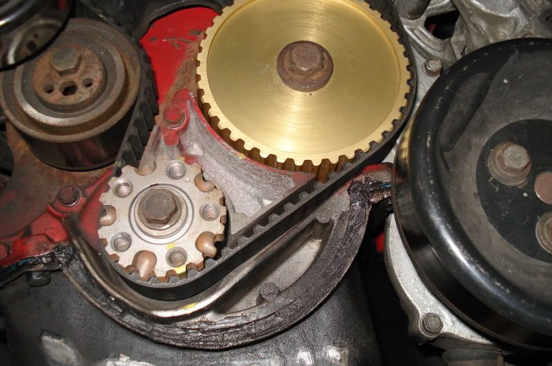
    I did use an 8 valve sprocket for over a year, didn't seem to do any damage to the belt etc, and yes, it isn't perfect fit but being in the place it is, it still works.

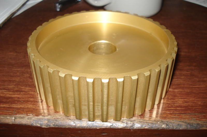
    Then I had someone whip this up for me, and he was supposed to make me a bunch but that didn't happen,


    Quote Originally Posted by 5DIGITS View Post
    Note that valuable belt length is being consumed. To counter-act this without the need for tensioner relocation, compare a production idler pulley to a tensioner-pulley and a significant commonality becomes apparent. The outer bearing race hub OD, on the idler, is incredibly close to the inner bearing race hub of the tensioner-pulley. With careful machining the outer tensioner-pulley OD can be eliminated and an adjustable idler is the result. This modified tensioner can be used in the standard location for an increase in usable belt length and also provides an additional belt/cam angle adjustment point, when installed on the front side of the engine. Adding an idler with minimal reverse flex loading while providing some increase in cam pulley belt wrap is a considerable improvement; while thorough rotational torque load reduction, balance shaft removal, and oil pump speed reduction can secure proven gains in durability.

    I hope this helps.
    Thanks
    Have you seen Jackson's mod, moving the idler pulley, its genius, lol.

    http://www.turbo-mopar.com/forums/sh...ad.php?t=28041
    1989 FWD Turbo Caravan-2.5 TIII, GT35R, auto, a/c, cruise, pwr windows/locks, fully loaded with interior and ran with full exhaust. RETIRED FOR A FEW YEARS! 12.57@104 :O)
    1984 Chev Getaway van, 6.2 Diesel with a remote mounted turbo setup burning WMO-For sale.
    2003 GSW 2.0L TDI, auto, fully loaded, modified, 360K-wife's.
    2004 GSW TDI, 5 speed, fully loaded, modified.

    Aurora ignition wires for sale. Link to info

    Super60 roller cams or custom/billet cams. Link to info

  17. #57
    Hybrid booster
    Join Date
    Dec 2008
    Location
    United States
    Posts
    857

    Re: T-III Reliability improvement

    Quote Originally Posted by BadFastGTC View Post
    I cannot recall, are the TIII keepers a multi-groove? If not, an offset keeper would be the hot ticket to add to the installed height.
    Hi Steve.
    The intakes are single groove while the exhausts are multi-groove.
    Hot ticket indeed, if possible.

    Keep in touch.
    Thanks

  18. #58
    turbo addict Pat's Avatar
    Join Date
    Dec 2005
    Location
    Rockville, MD
    Posts
    3,801

    Re: T-III Reliability improvement

    Quote Originally Posted by 5DIGITS View Post
    The .100" is important because when another groove is added, above the existing grooves (equally spaced), the retainer moves up .100", when the keepers utilize the new groove.

    Your second comment is correct, which is why we are discussing going from .075"-.085" retainer to a .100" stem-groove modification and then suggesting an additional increased retainer height.

    The T-III valve realizes approx. .100" less lift and has less back-side valve area. This reduces dutycycle severity and minimizes the spring pressure required, to overcome closing the valve.

    Thanks for your comments, Pat.
    I hope this helps.
    Got it...thanks for clarifying.

    I see the advantage lowering that spring pressure further, but at what closed pressure and rpm does float become a concern? Based on the valve size and lift, is there a closed spring pressure that you're targeting?

    I've run the raised retainers the vendors sell for years, which I think raises the spring height .070" and have had no belt, oil pump or I shaft bearing issues. I've also had no valve float issues running to 7000 or so. I'm wondering at what point does the float risk outweigh the benefits of lightening the spring.

  19. #59
    Buy my stuff!!!!!!!!!!! :O) Turbo Mopar Vendor turbovanman²'s Avatar
    Join Date
    Dec 2005
    Location
    Abbotsford, BC
    Posts
    44,167

    Re: T-III Reliability improvement

    Quote Originally Posted by Pat View Post
    Got it...thanks for clarifying.

    I see the advantage lowering that spring pressure further, but at what closed pressure and rpm does float become a concern? Based on the valve size and lift, is there a closed spring pressure that you're targeting?

    I've run the raised retainers the vendors sell for years, which I think raises the spring height .070" and have had no belt, oil pump or I shaft bearing issues. I've also had no valve float issues running to 7000 or so. I'm wondering at what point does the float risk outweigh the benefits of lightening the spring.

    Like I posted earlier, mine are close to S60 8 valve specs, no float at 7000+ rpm.
    1989 FWD Turbo Caravan-2.5 TIII, GT35R, auto, a/c, cruise, pwr windows/locks, fully loaded with interior and ran with full exhaust. RETIRED FOR A FEW YEARS! 12.57@104 :O)
    1984 Chev Getaway van, 6.2 Diesel with a remote mounted turbo setup burning WMO-For sale.
    2003 GSW 2.0L TDI, auto, fully loaded, modified, 360K-wife's.
    2004 GSW TDI, 5 speed, fully loaded, modified.

    Aurora ignition wires for sale. Link to info

    Super60 roller cams or custom/billet cams. Link to info

  20. #60
    turbo addict Pat's Avatar
    Join Date
    Dec 2005
    Location
    Rockville, MD
    Posts
    3,801

    Re: T-III Reliability improvement

    Quote Originally Posted by turbovanman View Post


    ]
    Hard to see in the picture, but is that pulley keyed?

Page 3 of 5 FirstFirst 12345 LastLast

Similar Threads

  1. SRT4 PCV Improvement
    By BadFastGTC in forum SRT-4 Neon & PT Cruiser
    Replies: 50
    Last Post: 10-04-2010, 12:36 PM

Posting Permissions

  • You may not post new threads
  • You may not post replies
  • You may not post attachments
  • You may not edit your posts
  •