Ok, I think I figured it out....
The code snipt below is the amount to change by...
Code:
; *****************************************
; For each cell, the first number is "rich", the second is "lean".
; If the O2 sensor is returning a lean value, "rich" kicks are added.
; If the O2 sensor is returning a rich value, "lean" kicks are added.
;
;     KICK - (factor * 512) - 512  (unsigned number)
; eg: $19  -   1.05  * 512  - 512 - 5%
; *****************************************
;          KICKS
;       Rich, Lean
    chem 4 n O2PrimaryRampKickCell0 x 0 65535 y Y 0 255 out PRIRMP Kick_Cell0_PrimaryRamp
    db  $1a,  $04       ; Cell 0
What I missed was key wording that says, if lean, then hit it with the rich kicks. If it is rich, then hit it with lean kicks. What that really says, that if it is below 0.35 volts (lean), as determined elsewhere in the code, then to hit it with $04 which is to make it push towards 0.55 volts (rich). If it is rich, then use $1A.
So it looks like you can adjust the O2 voltage limits in the code here...
Code:
O2HSWP_O2HighLimitForRampSwitching:
    chem 3 n O2HighLimitForRampSwitching O2 0 255 none Y 0 255 out O2HSWP Compared_with_raw_O2_sensor_signal_to_determine_toggle._$19_stock._O2_sensor_range_is_$00_to_$2f
    chem2 byte O2HSWP "Compared with Raw O2 signal for switching toggles. This is the high limit"
    db  $19
O2LSWP_O2LowLimitForRampSwitching:
    chem 3 n O2LowLimitForRampSwitching O2 0 255 none Y 0 255 out O2LSWP Compared_with_raw_O2_sensor_signal_to_determine_toggle._$18_stock._O2_sensor_range_is_$00_to_$2f
    chem2 byte O2LSWP "Compared with Raw O2 signal for switching toggles. This is the low limit"
    db  $18
; *****************************************
O2TLMH_O2HighLimitDelayedClosedLoop:
    chem 3 n O2HighLimitDelayedClosedLoop O2 0 255 none Y 0 255 out O2TLMH O2_Sensor_High_Limit_for_delayed_switch_to_closed_loop._$1f_stock._O2_sensor_range_is_$00_to_$2f
    chem2 byte O2TLMH "Compared with Raw O2 signal for Delayed switch to Closed Loop"
    db  $1f
O2TLML_O2LowLimitDelayedClosedLoop:
    chem 3 n O2LowLimitDelayedClosedLoop O2 0 255 none Y 0 255 out O2TLML O2_Sensor_Low_Limit_for_delayed_switch_to_closed_loop._$0f_stock._O2_sensor_range_is_$00_to_$2f
    chem2 byte O2TLML "Compared with Raw O2 signal for Delayed switch to Closed Loop"
    db  $0f
; *****************************************
O2MIDH_O2HighLimitForMidLevelDetermination:
    chem 3 n O2HighLimitForMidLevelDetermination O2 0 255 none Y 0 255 out O2MIDH O2_Sensor_High_Limit_for_In-Middle_determination._$1c_stock._O2_sensor_range_is_$00_to_$2f
    chem2 byte O2MIDH "Compared with Raw O2 signal for In-Middle determination"
    db  $1c
O2MIDL_O2LowLimitForMidLevelDetermination:
    chem 3 n O2LowLimitForMidLevelDetermination O2 0 255 none Y 0 255 out O2MIDL O2_Sensor_Low_Limit_for_In-Middle_determination._$12_stock._O2_sensor_range_is_$00_to_$2f
    chem2 byte O2MIDL "Compared with Raw O2 signal for In-Middle determination"
    db  $12
I think we would have to determine what the values like $1C or $12 relate too, but if I am right, they would just need to be scaled for the equivelent wideband voltages.
If that works, then we should be able to tighten up the ramp switching limits since rich and lean conditions are more clearly defined. By adjusting those, we won't need to touch the cells too much. We may have to reduce the kick sizes to ensure that you could fail at meeting the center of the rich/lean so that autocal would still work.
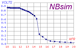
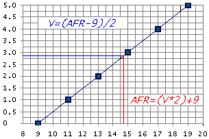
However there are some clitches. We would still need to use the NB out of our WB setups. So that we dont have to change the 'greater than' or 'less than' logics in the code. What we would need to do is modify the NB out to be the inverse of the WB. This would be because the A/D for the O2 sensor is more then likely not setup for the voltage levels of the WB out. In addition, the A/F to voltage is in the wrong direction.
So all in all, modify the NB out to be the inverse of the WB out. Modify the O2 limit values and then see how much you can tighten the kick and auto cal values.
OR I COULD BE CRAZY!


 Frank Katzenberger
 Reply With Quote


 .
.
