
- Turbo & Intercooler Systems
- G-valve Boost Controllers!
How To: G-valve Boost Controllers!
CAUTION! WARNING! CAUTION! WARNING!
DO NOT RAISE THE BOOST IN A CAR WITHOUT AN ACCURATE BOOST GAUGE!
DO NOT RAISE THE BOOST ABOVE FACTORY LEVELS WITHOUT ADDING ADDITIONAL FUEL!
CAUTION! WARNING! CAUTION! WARNING!
DO NOT RAISE THE BOOST IN A CAR WITHOUT AN ACCURATE BOOST GAUGE!
DO NOT RAISE THE BOOST ABOVE FACTORY LEVELS WITHOUT ADDING ADDITIONAL FUEL!
Over the years there have been many different types of home made boost controllers from using aquarium valves to simple vacuum line restrictions. One of the most commonly known and used type, especially in the Shelby Dodge and Turbo Mopar world is the G-Valve aka Grainger named after the foundation component, a check valve used and originally purchased from Grainer and also after one of the founding fathers of the design, Gus Mahon.
OK, lets get to it. First things first is your list of suggested tools:
- Lathe (or Dremel type tool)
- Band saw (or hack saw)
- 0.018 - 0.020 drill bit (yes, that tiny!)
- Drill press or mill or hand drill with VERY steady hands
- Bench vise with padding
- Crecent wrench
The required components are available at Grainer and other places too, the valve is a little hard to find but the barbed fittings are available at any good hardware stor. Because I have them handy, here are all of the McMaster Carr part numbers / package quantities.:
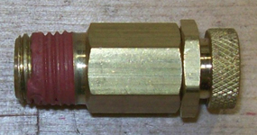
- Brass Adjustable Vacuum/Pressure Relief Valves - 48935K25 (1pc)
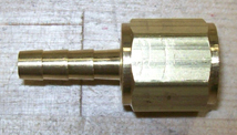
- Brass Fitting 3/16" Hose ID Barb X Female 1/4" NPT - 5346K51 (10pcs)
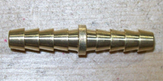
- Brass Barbed Hose Fitting Barb X Barb for 3/16" Hose ID - 91355K81 (5pcs)
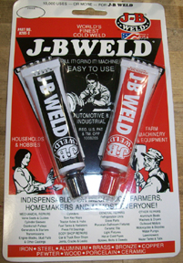
Additionally you will need some sort of cold-weld exopy such as JB Weld
STEP ONE:
Take the valve apart and swap the internals around. Out of the package the valve should be loosely screwed together, so simply unthread it carefully to make sure that the parts dont fly out and get lost. The components should be oriented similarly to the picture below.
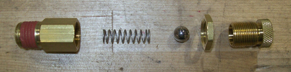
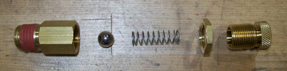
Take the ball and move it to the oposite side of the spring and re-assemble it opposite of how you took it apart. This step is the easiest one and can be completed at any stage in the procedure.
STEP TWO:
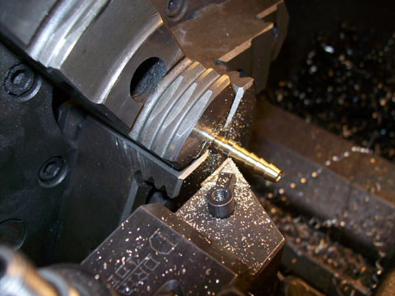
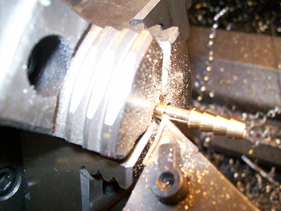
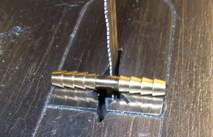
The next step is to take the double ended hose barb and make it into a single press-in barb. Measure the ID of the hole in the end of the valve and take the double ended barb and turn the middle portion down in a lathe. If a lathe is not used, you can VERY carefully grind it down to size using a Demel tool or equivalent. The goal is to make it the correct size to be a light press fit into the valve hole and also try to make it as round as possible for better sealing.
STEP THREE:
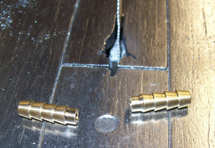
Once turned down to the correct size, the next step is to section it into two pieces. If you are planning to make only one G-Valve then you can simply cut it on one side of the turned down portion. If you plan to make two G-Valves and want to use both halves, VERY carefully cut it down the middle A band saw or hack saw can be used to do this. If you use a band saw, be very carefull that the blade, which sometimes wanders, does not cut off center or into your fingers!
STEP FOUR:
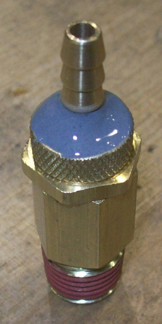
After the barb is sectioned into two pieces, take one half and press it into the hold on the end of the valve. A light press is desireable for valve durability so that it is not only held in by the JB Weld.
STEP FIVE:
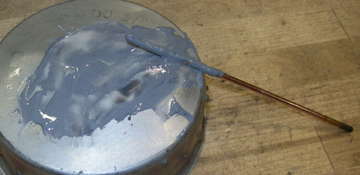
Once pressed in the next step is to mix up some JB Weld and glue the pressed in fitting in place. Mix equal parts of the dark epoxy and light hardener until they turn an even grey color. Then take your mixing stick and coat the end of the valve and stem on the barb about 1/4 way up or until the base of the next barb. The JB Weld needs to set up approximately 24 hours or at least overnight until it can be handles again.
STEP SIX:
The next step is to drill the vent hole. A vent hole is required so that the wastegate does not get stuck open. So that a vacuum leak is not formed, a very small 0.018 to 0.020 drill bit must be used. The best way to do this is with a precision drill press chuck with th evalve in a vise. If the drill slides around in teh chuck when it is fully tightened down, you can use tape around the bit to make the drills OD a little larger so the chuck can grab. Center the drill on the barb an dnear the end of the valve so that when the acuum line is on teh barb that teh vent hole is not covered. Start drilling through the JB weld because it is soft to start drilling in and act as a guide to hold the drill while drilling thru the brass. Continue drilling until the bit just breaks thru the surface. Be careful not to press too hard and slam the bit into the opposite side of the hole which may break the bit.
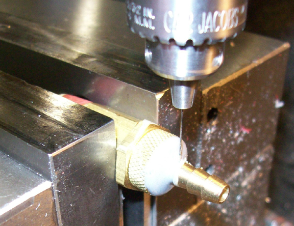
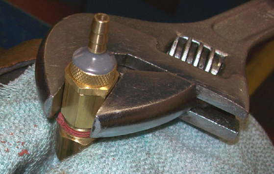
STEP SEVEN:
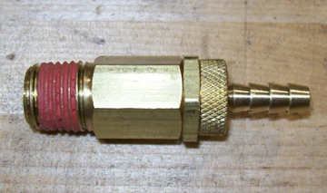
Once drilled, the final step is to assemble the barbed pipe fitting to the other end of the valve. The valve comes with thread sealant / thread lock already on it, but if yours does not, be sure to use teflon past or tape to seal the valve well. Assemble it by placing the barbed fitting into a bench vise with padding such as aluminum or coperr jaw pads and a soft rag. Then start threading the valve into it by hand. Once into the sealant you will have to use a wrench to thread it in the rest of the way. When it starts to get really tigth and almost no more threads left, try to align the flats of the hex on the valve to those of the barbed pipe fitting. This is not required, they just look nicer that way.
Your G-Valve is now assembled!
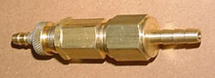
To use it, place in the wastegate actuator vacuum line close to the turbo wastegate actuator. The side of the G-Valve with teh vent hole goes to the actuator while the side with the ball goes towards the intake or factory boost control solenoid. The G-Valve screwed all the way out (longer) will be lower boost settings and screwed all teh way in (shorter) will allow for about 20psi. To obtain higher boost levels you can stretch the spring or swap a stiffer spring into the valve.

CAUTION! WARNING! CAUTION! WARNING!
DO NOT RAISE THE BOOST IN A CAR WITHOUT AN ACCURATE BOOST GAUGE!
DO NOT RAISE THE BOOST ABOVE FACTORY LEVELS WITHOUT ADDING ADDITIONAL FUEL!
This page has been seen 5,056 times.
-
-
Last updated by on
-