
- Drivetrain
- 3 Speed transmission Mods & Info
This is a work in progress, All information is being taken from here:http://www.turbo-mopar.com/forums/sh...l-in-one-place, the forum, or Archives of the Omniturbo.com webside and slowly put here. If you have any info you would like to add, reply to that thread.
Ill start off with the valve body mods, these are the easiest to do and usually the first to be done. Most of these can be done to a stock transmission as long as it is in good shape*. I will make a note if a modification shouldn't be done to a stock transaxle.
I will not cover things like removing the valve body, or disassembling the transaxle, an ATSG manual is a must and you should read and use one before doing any of these modifications. To find one just search "A404 A670 A413 ATSG Service manual"
If you are going to push your transmission (who isnt?) then a Good quality transmission cooler that bypasses the factory cooler is a great idea. Heat is the biggest killer of transmissions and a nice big cooler will help a lot. If you live in the colder parts of the world, hooking up the factory cooler after the aftermarket is a good idea.
To help with keeping the transmission alive inline magnetic transmission filters are available at the parts stores get one and put it on. This should be installed before the cooler if the cooler is new, if you are adding this after the cooler has been run for a while put it after.
A lot of these mods require the pan to removed frequently, a reusable trans pan gasket is a available from Mopar and makes life a lot easier, a drain plug can be installed making it even easier. The part number for the gasket is 05011113AA, the drain plug can be added by either welding a nut into the pan or using a commercially available kit.
All mods are assuming that The transmission is adjusted properly, both bands and the TV cable should be adjusted pretty much anytime the transmission is modified. The methods of adjustment are covered in the ATSG manual that you NEED. An alternative method for adjusting the bands will be covered later in this section.
The increased pressure of these mods puts a lot of stress on the rear band strut in low or reverse, Sonnax makes a heavy duty strut to prevent breaking this piece. If it brakes you will have no reverse, if it bends you will have a really slow to engage reverse. The Sonnax strut can be found by using its part number "32710-01"
Home made shift improver
Thanks again to Joe Dzwil for shift improvement suggestions. This is similar to the MP shift kit modifications, but not exactly the same.

The two large red spots on the left is where I block the accumulator. In the stock transmission, the accumulator acts to soften shifts, a no no. To block it I tapped the two holes in the transmission housing and screwed in a cut down screw to block the flow. The two very small red dots on the right were drilled out to 1/8th inch.

Notice that the accumulator ( the middle piston) is totally left out and the two holes feeding it are blocked by pieces of a cut off screw with a slot cut into it.
Follow this diagram for additional mods.

This diagram (minus the < I added) is from Garys page. As per the diagram, I removed one ball and added the 1.465" rod.. However, I also added a .187" ball or spacer inside Bypass valve spring to block it's movement. A ball bearing that is .187" or a .187 long obstruction that fits inside the spring will do. This got added where the < is above.
Raising the line pressure
The next step while you have the valve body out is to increase your line pressure, This increases the holding power of the clutches and raises shift points. I copied this from Chad Kilback's thread here: http://www.turbo-mopar.com/forums/showthread.php?6084-Line-pressure-mod-in-valve-body-and-theory
Note: When doing this mod, drill the hole so the fluid coming out of it goes away from the dipstick, it can make reading fluid level hard.
Note 2: when doing this to a stock transmission (without modified clutch packs) you should start very low, Start with a drill bit smaller that .046 and with the adjuster backed off. The problem is how loose the stock clutch packs are and if the pressure is too high they will slam into the retainer ring in the drum and blow the snap ring lip off the drum. The modifications will be covered later but keep the line pressure on a stock transmission only slightly over stock.
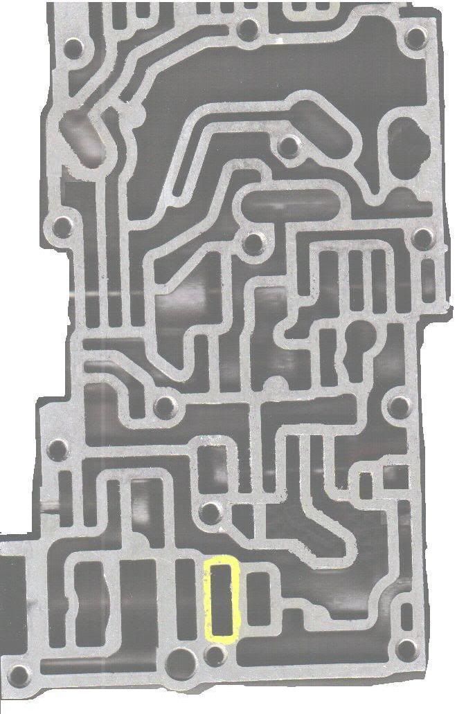
"Here's a mod that will up your line pressure beyond the max you can get out of it with the adjuster screw but without finding a new spring, buiding a spacer, etc. This will up line pressure in forward gears, but won't affect line pressure in reverse. Drill a hole in the passage marked in yellow. . . that's it. Drill it from the other side of the valve body though.
The theory of how the reg valve works and how the mod affects it:
This passage is where "one of two" of the "reaction areas" on the pressure regulator valve sit (a reaction area of a valve is the part of a valve where the oil pressure pushes on it to make it move). Oil is fed into this passage and pushes on the regulator valve. As the pressure builds up and reaches a certain pressure, the reg valve starts to move against the spring, until the valve opens up an exhaust port. This is how line pressure is created.
What does this mod do? It's easy if you think of it in turbo terms. The drilled hole is a "bleed". If you wanted to up the boost using a bleed, you'd put a restrictor in the wastegate line, and throw in a bleed valve. The hole that you drill in the valve body bleeds off some of the pressure, so *more* pressure has to build up to start moving the valve. The feed line to this passage is small enough that it can be considered a restrictor orifice.
As mentioned above, there are actually two passages and two reaction areas on the reg valve that the pressure tries to push on to move the valve. Pressure is fed to both passages (to try and move the reg valve) in all forward gears. But pressure does not get fed to this passage in reverse gear, which is why the line pressure jumps way up in reverse only, and is also why this mod won't affect the line pressure for reverse (which is a good thing).
How big of a hole to drill? I don't know exactly, as I haven't played with this mod on vb's other than my own. (I resized the feed hole (made the orifice smaller) on my mvb's so a "bleed" hole of .046" gives about 100 psi with the adjuster screw turned all the way in; and it give about 150psi at WOT). If I were to drill the bleed hole in any other valve body, I wouldn't go any bigger than a drill bit of 1/16", which is .062". This size bleed hole will probably get the pressure in the ball park of what I get. With this mod, each turn of the adjuster screw will result in a pressure change of around 5 psi (ultimately dependent on the size you go with the bleed hole). Have
fun drilling, and not having to worry about finding a new spring."
Now you need to put it together and take it for a test drive, see how it shifts and when it shifts. Probably shifts a little too High, this brings us to the next section.
Modifying the Governor

As the governor rotates, centrifugal force tries to push the valves (round circles in above) away from the center of the shaft while the line pressure tries to push them back in. If the weight of the valves in relation to the line pressure determines at what axle RPM the gears will shift. There are two differnt valves, a large diameter one and a small one. The larger valve (the one shown above) also has a helper spring to keep it pushed out. The stiffness of the spring also help determine the shift point. The orange spring (above right) is the stiffest, from a turbo. Also notice the the valve in the right photo is hollow so that it will be lighter.
Thanks again to Joe Dzwil, one of the very few guys who understands this tranny and is willing to share.

There are also a number of different weight versions of the smaller valve. Notice that some have a hole drilled for lightening and some are solid as well as some are thicker and some are thinner. The heavier the small valve, the lower the shift point. I currently use the lighter big valve (lightened just a bit more than stock turbo weight) and the orange (Turbo) spring and the middle weight small valve and seven turns of increased line pressure. I still need to do some more testing at higher boost levels, but I think I'm shifting just a bit too low. Maybe a little more line pressure will get me to where I need to be. I may have to shim the spring to get more pressure.
More info can be found on Governor modifications here: http://www.turbo-mopar.com/forums/sh...light=governor
Sonnax rear strut


The Sonnax HD band strut is shown here on the left, The one on the right can bend and cause a no/slow reverse issue. Part number can be found at the top of the page.
Front band Adjustment

This is where you will see the adjustment for the front band. The front band is what engages second gear. When pushing the transmission you need to adjust this differently than the the ATSG manual says to. To adjust, loosen the jam nut then tighten the adjusting bolt in until it is snug then back off 1.5 turns, this will put it where you need.
That pretty much wraps it up for stuff that can be done with the transmission in the car/van, this is usually where people stop and many run like this for years as most of these can actually extend the life of the transmission. If you push it and like to make power you will break or wear something out. This moves us on to the next section, benchtop mods.
Full on internal modifications
After the basic mods if you still want to push it or you pushed it too far already and you are doing a rebuild here are the mods to do while you are inside. These require the removal of the transmission and disassembly of the internal components, if you feel uneasy about doing this have someone help or do it for you. I will cover the modifications only in this section for a full rebuild you should have the ATSG manual mentioned earlier, this will give you wear specs and bearing replacement specs. Unless its covered here, see the manual.
Clutch pack Modifications

On the left is a rear clutch from a TBI car. Look carefully at the location of the grooves that hold the snap ring in place. The one from turbo and 6cyl trannies are spaced further out so that it can fit the four stock clutches. The rear clutch can stay stock, but the turbo/v6 unit (also neon) is needed, they are 4 clutch units. The reason this can stay stock is that this clutch is never shifted under power (as long as you shift sitting still). Once you put the car in any forward gear this clutch is applied and doesn't release, Just use stock replacement parts in this clutch and follow the ATSG for the overhaul. Note: this clutch is also called the forward clutch, don't get that confused it is only because it powers all forward gears.

On the left is a front clutch (also called direct clutch) from a TBI car. Look carefully at the location of the grooves that hold the snap ring in place. The one from turbo and 6cyl trannies are spaced further out (just like in the rear clutch packs) so that it can fit the four stock clutches. Don't bother trying to add more clutches to the TBI parts.
The front clutch is where we need to upgrade, the front clutch is what engages third gear thus why it is also called the direct clutch. To upgrade the front clutch we need to source some parts

Note that the planetary gear case on the left has shorter splines and cannot be used with extra clutches. Make sure the case used fully engages all of the splines and clutches.
Front Band

The amount of clamping force on the front clutch pack can be varied by changing the levers distance from the pivot point to the groove where the small H strut rests. I think the upper one (less force) came from a TBI car. The middle one from Turbo or V6 and the one on the bottom is a turbo one I modified to make the groove slightly closer to give more clamping power.

If you're going to have more clamping power from changing the lever or increasing your line pressure, then you'll need to beef up the front clutch band as well. The three small tack welds on the one on the left separated resulting in 2nd gear slip. I reinforced the replacement with extra welds to beef it up. A picture of the welds can be seen under the shift improver section. Adjustment for the band is as follows, tighten until snug then back off 1.5 turns.
Planetary gears

96 and later 3 speed trannies contain a five gear planetary gear (the one on the left). I'm told that these fail as often as the four gear ones because the puny welds that hold the gears axles give out. If you look above, on the right, you can see that only a small part of the each axle is tack welded to the carrier. I've seem remanufactured units have the weld go all the way around each of the axles. I've re-welded the axles in mine and went with the five gear unit.

Stay away from the planetary gears the have a round carrier like the one on the right. It appears to be made of cast material and I've been told they don't hold up at all.
Differential
One of the common problems with the A413 tranny is the differential bearing. I didn't replace my bearings (each were over 120,000 miles) or preload the tension on them, so it's not surprising that with the additional horsepower, my bearings failed.

Typical A413 bearing (one on the right above), likely gets the most load of all bearings in the tranny and I hear they usually only last about 60,000 miles under normal load. Joe Dzwil told me that in 1996, Chrysler introduced a beefier version of the differential with a bigger bearing on the gear side in the 3 speed trannies. On the left is the bigger 1996 or later diff and bearing mount. These bolt right in. By the way, in the 97 3 speed tranny where I found this diff, the ring gear was larger and the pinion smaller than those in the A413s. This combo can be used to alter the final drive ratio as well as changing the transfer gears. I stuck with the original 2.86 ring/pinion gear ratio from the 89 turbo tranny because I want to reduce the potential for tire spin and a higher top end potential speed and also lower rpm highway driving.

A Differential pin retainer of some type other than the stock roll pin is a must. One of my early mistakes was to weld a washer to each side of the differential pin in order to keep it from walking out of the carrier. Well, the weld didn't hold and the washer came loose and got mashed between the ring and pinion gears. Result = cracked case. I've been told that if you're going to weld a washer to keep the pin in, weld it to the carrier and not the pinion shaft and use nickel welding rod which works well with the cast carrier material. BTW, Chrysler now makes hardened rods which many tranny pros use instead of the roll pins (for stock production rebuilds). There are differing opinions about leaving the roll pin out altogether if you use some other, external means of keeping the differential pin from walking.

the part number for these brackets are 04800059AA
Ill start off with the valve body mods, these are the easiest to do and usually the first to be done. Most of these can be done to a stock transmission as long as it is in good shape*. I will make a note if a modification shouldn't be done to a stock transaxle.
I will not cover things like removing the valve body, or disassembling the transaxle, an ATSG manual is a must and you should read and use one before doing any of these modifications. To find one just search "A404 A670 A413 ATSG Service manual"
If you are going to push your transmission (who isnt?) then a Good quality transmission cooler that bypasses the factory cooler is a great idea. Heat is the biggest killer of transmissions and a nice big cooler will help a lot. If you live in the colder parts of the world, hooking up the factory cooler after the aftermarket is a good idea.
To help with keeping the transmission alive inline magnetic transmission filters are available at the parts stores get one and put it on. This should be installed before the cooler if the cooler is new, if you are adding this after the cooler has been run for a while put it after.
A lot of these mods require the pan to removed frequently, a reusable trans pan gasket is a available from Mopar and makes life a lot easier, a drain plug can be installed making it even easier. The part number for the gasket is 05011113AA, the drain plug can be added by either welding a nut into the pan or using a commercially available kit.
All mods are assuming that The transmission is adjusted properly, both bands and the TV cable should be adjusted pretty much anytime the transmission is modified. The methods of adjustment are covered in the ATSG manual that you NEED. An alternative method for adjusting the bands will be covered later in this section.
The increased pressure of these mods puts a lot of stress on the rear band strut in low or reverse, Sonnax makes a heavy duty strut to prevent breaking this piece. If it brakes you will have no reverse, if it bends you will have a really slow to engage reverse. The Sonnax strut can be found by using its part number "32710-01"
Home made shift improver
Thanks again to Joe Dzwil for shift improvement suggestions. This is similar to the MP shift kit modifications, but not exactly the same.
The two large red spots on the left is where I block the accumulator. In the stock transmission, the accumulator acts to soften shifts, a no no. To block it I tapped the two holes in the transmission housing and screwed in a cut down screw to block the flow. The two very small red dots on the right were drilled out to 1/8th inch.
Notice that the accumulator ( the middle piston) is totally left out and the two holes feeding it are blocked by pieces of a cut off screw with a slot cut into it.
Follow this diagram for additional mods.
This diagram (minus the < I added) is from Garys page. As per the diagram, I removed one ball and added the 1.465" rod.. However, I also added a .187" ball or spacer inside Bypass valve spring to block it's movement. A ball bearing that is .187" or a .187 long obstruction that fits inside the spring will do. This got added where the < is above.
Raising the line pressure
The next step while you have the valve body out is to increase your line pressure, This increases the holding power of the clutches and raises shift points. I copied this from Chad Kilback's thread here: http://www.turbo-mopar.com/forums/showthread.php?6084-Line-pressure-mod-in-valve-body-and-theory
Note: When doing this mod, drill the hole so the fluid coming out of it goes away from the dipstick, it can make reading fluid level hard.
Note 2: when doing this to a stock transmission (without modified clutch packs) you should start very low, Start with a drill bit smaller that .046 and with the adjuster backed off. The problem is how loose the stock clutch packs are and if the pressure is too high they will slam into the retainer ring in the drum and blow the snap ring lip off the drum. The modifications will be covered later but keep the line pressure on a stock transmission only slightly over stock.
"Here's a mod that will up your line pressure beyond the max you can get out of it with the adjuster screw but without finding a new spring, buiding a spacer, etc. This will up line pressure in forward gears, but won't affect line pressure in reverse. Drill a hole in the passage marked in yellow. . . that's it. Drill it from the other side of the valve body though.
The theory of how the reg valve works and how the mod affects it:
This passage is where "one of two" of the "reaction areas" on the pressure regulator valve sit (a reaction area of a valve is the part of a valve where the oil pressure pushes on it to make it move). Oil is fed into this passage and pushes on the regulator valve. As the pressure builds up and reaches a certain pressure, the reg valve starts to move against the spring, until the valve opens up an exhaust port. This is how line pressure is created.
What does this mod do? It's easy if you think of it in turbo terms. The drilled hole is a "bleed". If you wanted to up the boost using a bleed, you'd put a restrictor in the wastegate line, and throw in a bleed valve. The hole that you drill in the valve body bleeds off some of the pressure, so *more* pressure has to build up to start moving the valve. The feed line to this passage is small enough that it can be considered a restrictor orifice.
As mentioned above, there are actually two passages and two reaction areas on the reg valve that the pressure tries to push on to move the valve. Pressure is fed to both passages (to try and move the reg valve) in all forward gears. But pressure does not get fed to this passage in reverse gear, which is why the line pressure jumps way up in reverse only, and is also why this mod won't affect the line pressure for reverse (which is a good thing).
How big of a hole to drill? I don't know exactly, as I haven't played with this mod on vb's other than my own. (I resized the feed hole (made the orifice smaller) on my mvb's so a "bleed" hole of .046" gives about 100 psi with the adjuster screw turned all the way in; and it give about 150psi at WOT). If I were to drill the bleed hole in any other valve body, I wouldn't go any bigger than a drill bit of 1/16", which is .062". This size bleed hole will probably get the pressure in the ball park of what I get. With this mod, each turn of the adjuster screw will result in a pressure change of around 5 psi (ultimately dependent on the size you go with the bleed hole). Have
fun drilling, and not having to worry about finding a new spring."
Modifying the Governor
As the governor rotates, centrifugal force tries to push the valves (round circles in above) away from the center of the shaft while the line pressure tries to push them back in. If the weight of the valves in relation to the line pressure determines at what axle RPM the gears will shift. There are two differnt valves, a large diameter one and a small one. The larger valve (the one shown above) also has a helper spring to keep it pushed out. The stiffness of the spring also help determine the shift point. The orange spring (above right) is the stiffest, from a turbo. Also notice the the valve in the right photo is hollow so that it will be lighter.
Thanks again to Joe Dzwil, one of the very few guys who understands this tranny and is willing to share.
There are also a number of different weight versions of the smaller valve. Notice that some have a hole drilled for lightening and some are solid as well as some are thicker and some are thinner. The heavier the small valve, the lower the shift point. I currently use the lighter big valve (lightened just a bit more than stock turbo weight) and the orange (Turbo) spring and the middle weight small valve and seven turns of increased line pressure. I still need to do some more testing at higher boost levels, but I think I'm shifting just a bit too low. Maybe a little more line pressure will get me to where I need to be. I may have to shim the spring to get more pressure.
More info can be found on Governor modifications here: http://www.turbo-mopar.com/forums/sh...light=governor
Sonnax rear strut
The Sonnax HD band strut is shown here on the left, The one on the right can bend and cause a no/slow reverse issue. Part number can be found at the top of the page.
Front band Adjustment
This is where you will see the adjustment for the front band. The front band is what engages second gear. When pushing the transmission you need to adjust this differently than the the ATSG manual says to. To adjust, loosen the jam nut then tighten the adjusting bolt in until it is snug then back off 1.5 turns, this will put it where you need.
That pretty much wraps it up for stuff that can be done with the transmission in the car/van, this is usually where people stop and many run like this for years as most of these can actually extend the life of the transmission. If you push it and like to make power you will break or wear something out. This moves us on to the next section, benchtop mods.
Full on internal modifications
After the basic mods if you still want to push it or you pushed it too far already and you are doing a rebuild here are the mods to do while you are inside. These require the removal of the transmission and disassembly of the internal components, if you feel uneasy about doing this have someone help or do it for you. I will cover the modifications only in this section for a full rebuild you should have the ATSG manual mentioned earlier, this will give you wear specs and bearing replacement specs. Unless its covered here, see the manual.
Clutch pack Modifications
On the left is a rear clutch from a TBI car. Look carefully at the location of the grooves that hold the snap ring in place. The one from turbo and 6cyl trannies are spaced further out so that it can fit the four stock clutches. The rear clutch can stay stock, but the turbo/v6 unit (also neon) is needed, they are 4 clutch units. The reason this can stay stock is that this clutch is never shifted under power (as long as you shift sitting still). Once you put the car in any forward gear this clutch is applied and doesn't release, Just use stock replacement parts in this clutch and follow the ATSG for the overhaul. Note: this clutch is also called the forward clutch, don't get that confused it is only because it powers all forward gears.
On the left is a front clutch (also called direct clutch) from a TBI car. Look carefully at the location of the grooves that hold the snap ring in place. The one from turbo and 6cyl trannies are spaced further out (just like in the rear clutch packs) so that it can fit the four stock clutches. Don't bother trying to add more clutches to the TBI parts.
The front clutch is where we need to upgrade, the front clutch is what engages third gear thus why it is also called the direct clutch. To upgrade the front clutch we need to source some parts
Note that the planetary gear case on the left has shorter splines and cannot be used with extra clutches. Make sure the case used fully engages all of the splines and clutches.
Front Band
The amount of clamping force on the front clutch pack can be varied by changing the levers distance from the pivot point to the groove where the small H strut rests. I think the upper one (less force) came from a TBI car. The middle one from Turbo or V6 and the one on the bottom is a turbo one I modified to make the groove slightly closer to give more clamping power.
If you're going to have more clamping power from changing the lever or increasing your line pressure, then you'll need to beef up the front clutch band as well. The three small tack welds on the one on the left separated resulting in 2nd gear slip. I reinforced the replacement with extra welds to beef it up. A picture of the welds can be seen under the shift improver section. Adjustment for the band is as follows, tighten until snug then back off 1.5 turns.
Planetary gears
96 and later 3 speed trannies contain a five gear planetary gear (the one on the left). I'm told that these fail as often as the four gear ones because the puny welds that hold the gears axles give out. If you look above, on the right, you can see that only a small part of the each axle is tack welded to the carrier. I've seem remanufactured units have the weld go all the way around each of the axles. I've re-welded the axles in mine and went with the five gear unit.
Stay away from the planetary gears the have a round carrier like the one on the right. It appears to be made of cast material and I've been told they don't hold up at all.
Differential
One of the common problems with the A413 tranny is the differential bearing. I didn't replace my bearings (each were over 120,000 miles) or preload the tension on them, so it's not surprising that with the additional horsepower, my bearings failed.
Typical A413 bearing (one on the right above), likely gets the most load of all bearings in the tranny and I hear they usually only last about 60,000 miles under normal load. Joe Dzwil told me that in 1996, Chrysler introduced a beefier version of the differential with a bigger bearing on the gear side in the 3 speed trannies. On the left is the bigger 1996 or later diff and bearing mount. These bolt right in. By the way, in the 97 3 speed tranny where I found this diff, the ring gear was larger and the pinion smaller than those in the A413s. This combo can be used to alter the final drive ratio as well as changing the transfer gears. I stuck with the original 2.86 ring/pinion gear ratio from the 89 turbo tranny because I want to reduce the potential for tire spin and a higher top end potential speed and also lower rpm highway driving.
A Differential pin retainer of some type other than the stock roll pin is a must. One of my early mistakes was to weld a washer to each side of the differential pin in order to keep it from walking out of the carrier. Well, the weld didn't hold and the washer came loose and got mashed between the ring and pinion gears. Result = cracked case. I've been told that if you're going to weld a washer to keep the pin in, weld it to the carrier and not the pinion shaft and use nickel welding rod which works well with the cast carrier material. BTW, Chrysler now makes hardened rods which many tranny pros use instead of the roll pins (for stock production rebuilds). There are differing opinions about leaving the roll pin out altogether if you use some other, external means of keeping the differential pin from walking.
the part number for these brackets are 04800059AA
This page has been seen 8,775 times.
-
-
Created by onLast updated by on
-